ACTIVE TREATMENTS
Overview
Active traffic control devices are those that give visual and audible advance notice of the approach of a train. These include flashing-light signals (both mast-mounted and cantilevered), bells, automatic gates, active advance warning devices, and highway traffic signals. Active devices are typically activated by the passage of a train over a detection circuit in the track, except in those few situations where manual control or manual operation is used (LRT systems typically use loops or contacts because LRT tracks are used as an electrical "ground" to propel trains). Active traffic control devices are usually supplemented with the same signs and pavement markings used for passive control, except that STOP or YIELD signs are not used where active traffic control devices are installed. This section describes the different traffic control devices available for use. Additional guidance on the selection of alternatives can be found in Chapter 3.
Driving tasks at crossings with active traffic control devices are different from those at crossings with passive devices. Passive devices indicate that a crossing is present and that it is the road user's responsibility to look for an approaching train and take appropriate action. At crossings with active traffic control devices, a motorist is told when a train is approaching or is present at the crossing. It is the motorist's responsibility to take appropriate action when the devices are activated.
Train Detection and Device Activation
Devices need to be actuated in advance of train arrival to allow road users to clear the track area. A key principle is "warning time"–the amount of advance notice of the arrival of a train. In addition to the time for road users to perceive and react to active warning devices and for pedestrians and vehicles to clear the tracks, active control devices present at a crossing must activate and operate in a logical sequence which may include "preemption" of downstream traffic signals to allow vehicles to clear from the crossing, as well as activation of flashing-light devices and bells followed by descent of the crossing gates, if present.
Active devices are actuated by means of train detection circuitry. Legacy train detection units rely upon conventional electronic components including coils, resistors, and relays. Current train detection is largely solid state driven, but the outputs are taken from relays activated by the solid state circuits. Shown in Figure 20, the fundamental concept is use of a railroad circuit which uses the rails as conductors. A voltage is applied across the rails at one end of a detection zone and a relay (or other circuitry) detects the voltage transmitted down the rails. The presence of a solid electrical path, as provided by the wheels and axles of a locomotive or railroad car, shunts (closes) the circuit, which causes the detection relay to trip.
The system is also designed to be fail-safe; that is, any shunt of the circuit, whether by railroad equipment, vandalism, or an "open circuit" (e.g., a broken rail or track connection), will open the relay, which causes the crossing signals to be activated.
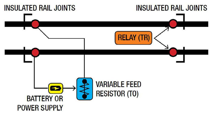
Source: Adapted from Minor Railways Section Guideline on Train Detection DC Track Circuits, Figure 1, Institute of Railway Signal Engineers, 2014.
Standard highway traffic signals always display a green, yellow, or red light except when power has failed and the signals are dark. Active crossing warning devices, however, usually incorporate some "fail-safe" design principles. In other words, the crossing warning system is designed to give an indication of an approaching train whenever the system fails. Crossing signals are normally dark unless a train is approaching or occupying the crossing, so there is no indication to the road user when power has failed. Therefore, crossing control systems include stand-by battery power should commercial power be terminated for any reason. Solar energy may be used to charge storage batteries to power signals at crossings in remote locations.
Factors that may be considered in the design and installation of a train detection system include the following:
- Existing rail and ballast conditions
- Volume, speed, and type of highway and rail traffic
- Other train detection circuits that may be used on the same pair of rails for the regulation of train movements
- Train propulsion currents on electrified lines
- Track switch locations within the approach warning distances for a crossing
- Train detection circuits used for other crossings within the approaches (overlapping)
- Number of tracks
- Warning time and system credibility
Constant Warning Time Track Circuit
Train detection systems are designed to provide the minimum warning time for a crossing. The MUTCD and FRA regulations (49 CFR 234.225) require that the system provide for a minimum of 20 seconds of warning time. When determining if the minimum 20 seconds of warning time should be increased, some factors that should be considered include but are not limited to the following:
Where constant warning time is provided, the track circuitry equipment has the capability to sense a train in the approach section, measure its speed and distance from the crossing, and activate the warning equipment to provide the selected minimum warning time. Thus, regardless of train speed, a uniform warning time is provided. If a train stops prior to reaching the crossing or is moving away from the crossing, the warning devices are deactivated to allow highway traffic to move over the crossing. With constant warning time equipment, trains beyond 700 feet can move or switch on the approaches without reaching the crossing, and depending on their speed, not cause the crossing warning devices to be activated, thus eliminating unnecessary delays to highway traffic.
Warning Time Considerations
- Track clearance distances due to multiple tracks and/or angled crossings (add 1 second for each 10 feet of added crossing length in excess of 35 feet).
- The crossing is located within proximity of a highway intersection controlled by STOP signs where vehicles have a tendency of stopping on the crossing.
- The crossing is regularly used by long tractor-trailer vehicles.
- The crossing is regularly used by vehicles required to make mandatory stops before proceeding over the crossing (such as school buses and hazardous materials vehicles).
- The crossing's active traffic control devices are interconnected with other highway traffic signal systems.
- It is necessary to provide at least 5 seconds between the time the approach lane gates to the crossing are fully lowered and when the train reaches the crossing (49 CFR 234.223).
- The crossing is regularly used by pedestrians and non-motorized components.
- The crossing and approaches are not level.
- Additional warning time is needed to accommodate a four-quadrant gate system.
- Other factors regarding crossing location as appropriate.
It should be noted that even when constant warning devices are used, the calculated arrival time of the train at the crossing is based on the instantaneous speed of the train as it enters the crossing circuit. Once the calculation is made, changes in the train speed will change the train arrival time at the crossing and, correspondingly, reduce (or increase) the elapsed warning time at the crossing. This factor must be considered at a crossing interconnected to a nearby highway traffic signal utilizing either a simultaneous or advance preemption sequence.
Excessive warning time has been determined to be a contributing factor in some collisions. Motorists who are stopped at an activated flashing-light signal and see no train approaching or see a distant train moving very slowly might ignore the warning of the signals and cross the tracks. A collision could result as the signals may have been activated by a high-speed passenger train just out of sight, not by the slower freight. If motorists are successful in clearing the tracks, they may assume that other crossings have excessive warning time. When they encounter a crossing with minimum warning time, they may ignore the signals, move onto the crossing, and become involved in a collision. This credibility problem is strengthened if motorists continue to successfully pass through activated signals with excessive warning time.
Reasonable and consistent warning times reinforce system credibility. Unreasonable or inconsistent warning times may encourage undesirable driver behavior. Research has shown that when warning times exceed 40-50 seconds, drivers will accept shorter clearance times at flashing-lights and a significant number will attempt to drive around gates.(28) Although mandated maximum warning times do not yet exist, efforts should be made to ensure that traffic interruptions are reasonable and consistent without compromising the intended safety function of an active control device system's design.
Excessive warning times are associated with a permanent reduction in the class of track and/or train speeds without a concomitant change in the track circuitry or without constant warning time equipment. When not using constant warning train detection systems, track approach circuits should be adjusted accordingly when train speeds are permanently reduced. Another frequent cause of excessive warning times at crossings without constant warning time equipment is variable-speed trains, such as intercity passenger trains or fast commuter trains interspersed with slower freight trains.
A major factor affecting system credibility is an unusual number of false activations at active crossings. Every effort should be made to minimize false activations through improvements in track circuitry, train detection equipment, and maintenance practices. A timely response to a system malfunction coupled with repairs made without undue delay can reduce credibility issues. Health monitoring systems capable of reporting to dispatch can improve response times.
Design information about railroad interconnection circuits and approach length calculations can be found in the AREMA Communications and Signals Manual, Part 3.1.10, "Recommended Functional/Operating Guidelines for Interconnection Between Highway Traffic Signals and Highway-Rail Grade Crossing Warning Systems," and Part 3.3.10, "Recommended Instructions for Determining Warning Time and Calculating Minimum Approach Distance for Highway-Rail Grade Crossing Warning Systems."(29)
FLASHING-LIGHT SIGNALS
The fundamental active warning device is the flashing-light signal, refer to Figure 21, which shows the unit combined with an automatic crossing gate. Flashing-light signals consist of two light units that flash alternately at a rate of 35 to 65 times per minute. The signal lens is red and comes in a variety of designs that direct the light toward the motorist. The lamp consists of a low-wattage bulb (legacy units) or LED assembly (current practice) used to ensure operation on stand-by battery power should commercial power fail.
The LED units used in new installations offer many advantages over conventional incandescent lamps including the following:
- Higher visibility at greater distances for in-line observations
- Greater visibility on angles
- Wider beam pattern and therefore easier beam alignment
- Pure red signal with fast on/off transition, which improves conspicuity
- Lower current consumption at nominal voltage, thereby suitable for solar-powered applications
- Longer life expectancy
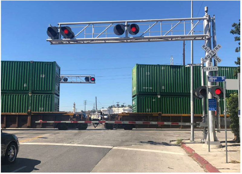
Source: Brent Ogden.
Key MUTCD requirements (refer to Part 8C.02) include the following:
- If used, the flashing-light signal assembly on the side of the highway shall include a standard Crossbuck (R15-1) sign, and, where there exists more than one track, a supplemental Number of Tracks (R15-2P) plaque, all of which indicate to motorists, bicyclists, and pedestrians the location of a crossing.
- The flashing-light signal shall display toward approaching highway traffic two red lights mounted in a horizontal line flashing alternately.
- Flashing-light signals shall be placed to the right of approaching highway traffic on all highway approaches to a crossing. They shall be located laterally with respect to the highway in compliance with MUTCD Figure 8C-1 except where such location would adversely affect signal visibility.
- If used at a crossing with highway traffic in both directions, back-to-back pairs of lights shall be placed on each side of the tracks. On multi-lane one-way streets and divided highways, flashing-light signals shall be placed on the approach side of the crossing on both sides of the roadway or shall be placed above the highway.
- MUTCD requires 12-inch lenses for all new installations excepting signals controlling pedestrian movements; however, where 8-inch units are already in place they may be retained for the remainder of their useful service life.
Other MUTCD guidance includes the following:
- At highway-rail crossings, bells or other audible warning devices may be included in the assembly as determined by a Diagnostic Team and may be operated in conjunction with the flashing-lights to provide additional warning for pedestrians, bicyclists, and/or other non-motorized road users.
- If determined by a Diagnostic Team, flashing-light signals may be installed on overhead structures or cantilevered supports, as shown in Figure 21, where needed for additional emphasis, or for better visibility to approaching traffic, particularly along multi-lane approaches or highways with profile restrictions. If it is determined by a Diagnostic Team that one set of flashing-lights on the cantilever arm is not sufficiently visible to road users, one or more additional sets of flashing-lights may be mounted on the supporting post and/or on the cantilever arm.
Current practice is to provide one flashing-light signal directed at each approach lane which may require use of an overhead cantilever and to provide supplemental flashing-light units aimed at frontage road approaches, as discussed below.
Proper alignment of the light is essential. The following guidance on aiming lights was developed originally for highly directional 12-volt bulbs and reflectors. Current LED equipment, however, is more tolerant on the precision of aiming. Nevertheless, the aiming principles described should be followed. The flashing-light unit on the right-hand side of the highway is usually aligned to cover a distance far from the crossing. The light units mounted on the back of the signals on the opposing approach and, thus, on the left, are usually aligned to cover the near approach to the crossing. Figure 22 shows typical alignment patterns for a two-lane, two-way highway and for a multilane highway.
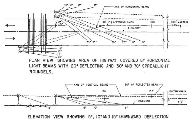
Source: Communications & Signals Manual, Figure 335-1, Lanham, MD, AREMA, 2018.
Cantilevered Flashing-Light Signals
Flashing-light signals are post-mounted, but where improved visibility to approaching traffic is required, cantilevered flashing-light signals are used. Cantilevered flashing-lights may be appropriate when any of the following conditions exist:
- Multilane highways (two or more lanes in one direction)
- Highways with paved shoulders or a parking lane that would require a post-mounted light to be more than 10 feet from the edge of the travel lane
- Roadside foliage obstructing the view of post-mounted flashing-light signals
- A line of roadside obstacles such as utility poles (when minor lateral adjustment of the poles would not solve the problem)
- Distracting backgrounds such as an excessive number of neon signs (conversely, cantilevered flashing-lights should not distract from nearby highway traffic signals)
- Horizontal or vertical curves at locations where the extension of flashing-lights over the traffic lane will provide sufficient visibility for the required stopping sight distance
A typical installation consists of one pair of cantilevered lights on each highway approach, supplemented with a pair of lights mounted on the supporting mast. However, two or more pairs of cantilevered flashing-lights may be desirable for multilane approaches, as determined by an engineering study. The cantilevered lights can be placed over each lane so that the lights are mutually visible from adjacent driving lanes.
Most current installations utilize walkout cantilevers. The inclusion of a ladder and access walkway allows for easier maintenance with less impact to highway traffic. Standard cantilevers for mounting flashing-lights are made with arm lengths up to 40 feet. Where cantilever arm length is more than 35 feet, a bridge structure is preferred.
Supplemental Flashing-Light Signals
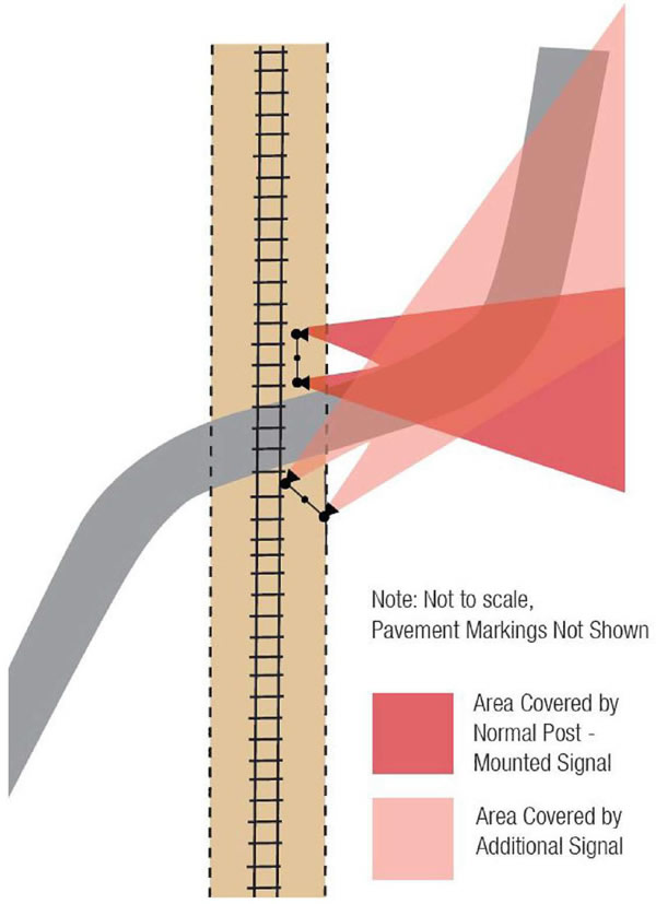
Additional pairs of light units, sometimes referred to as "side lights" may also be installed for side roads intersecting the approach highway near the crossing or for horizontal curves. Figure 23 shows the use of multiple pairs of lights to cover a horizontal curve to the left on the approach highway. A horizontal curve to the right may be covered by placing another roadside flashing-light unit on the opposite side of the highway, as shown in Figure 24. Figure 25 shows the use of side lights to provide warning to road users approaching from frontage roadways parallel the railroad. Mounting of angled side light units should maintain the 30-inch spacing indicated in MUTCD Figure 8C-1 from the vantage point of the road user.
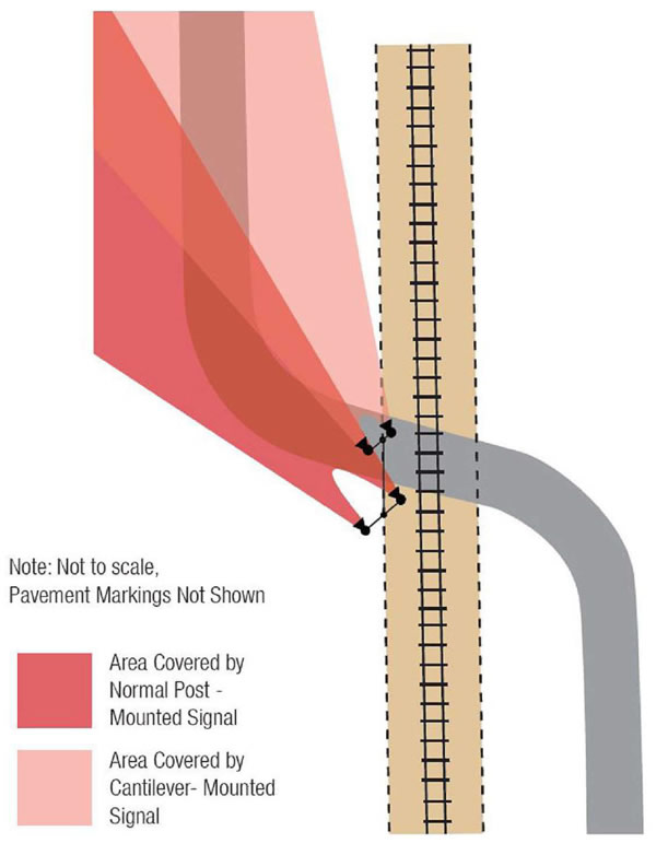
Source: Institute of Transportation Engineers.
Source: Institute of Transportation Engineers.
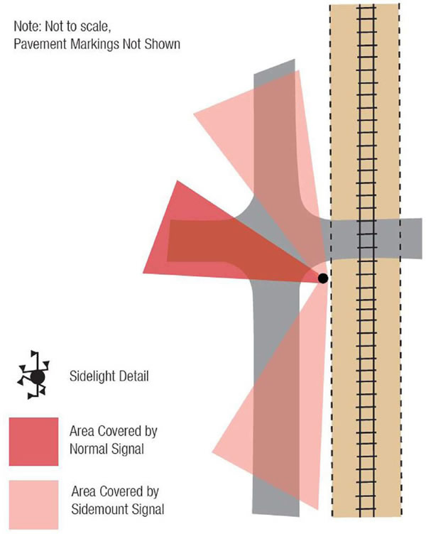
Source: Institute of Transportation Engineers.
AUDIBLE WARNING
A crossing bell is an audible warning device used to supplement other active traffic control devices. A bell is most effective as a warning to pedestrians and bicyclists.
When used, the bell is usually mounted on top of one of the signal support masts. Alternatively, the bell may be separately mounted on an arm attached to the signal mast. The bell is usually activated whenever the flashing-light signals are operating. Bell circuitry may be designed so that the bell stops ringing when the lead end of the train reaches the crossing. When gates are used, the bell may be silenced when the gate arms descend to within 10 degrees of the horizontal position. Silencing the bell when the train reaches the crossing or when the gates are down may be desired to accommodate residents of suburban areas.
Crossing bell specifications indicate a range of a minimum of 75 dB(A) and a maximum of 105 dB(A). AREMA specifications detail how these measurements are taken, including the following:
- Bell should operate between 100 and 325 strokes per minute.
- Electronic bells should emulate the sound of electro-mechanical bells.
- Practitioners should decide as to whether one audible device is adequate to serve the entire crossing or if a second bell should be added at large crossings.
In addition to the audible device(s) provided at the crossing, FRA requires the sounding of locomotive mounted horns in advance of crossing occupancy by a train. Refer to "Requirement to Sound the Locomotive Horn" within the "Quiet Zones" topic in Chapter 6 for additional guidance.
Wayside Horn
Another form of audible warning is the wayside horn. The wayside horn system consists of a horn or series of horns located at a public highway-rail crossing and directed at oncoming motorists. (Refer to Figure 26 which shows a typical installation using two horns to alert road users approaching from each direction.) The system is designed on fail-safe principles and provides a means to verify sound output. The wayside horn system does the following:
- Simulates the sound and pattern of a train horn
- Provides similar response from road users
- Minimizes the audible footprint in comparison to a locomotive horn sounding when approaching a highway-rail crossing
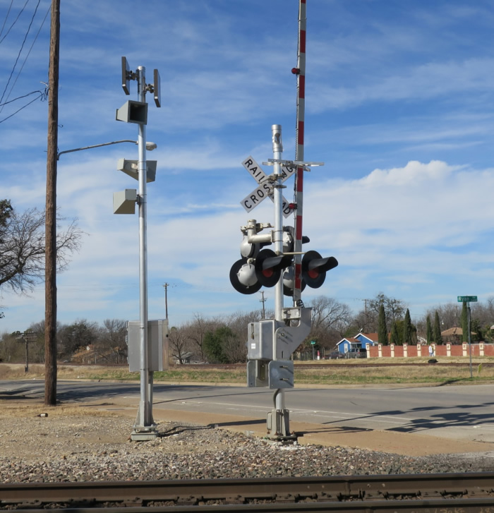
Source: Campbell Technology Corporation.
A wayside horn system can be used as an adjunct to train-activated crossing warning systems to provide audible warning of an approaching train for traffic on each approach to the highway-rail crossing. Wayside horns provide a directional sound which is aimed at approaching roadway users and pedestrians while minimizing the noise impact to properties adjacent to the railroad beyond the immediate crossing zone. (The wayside horn system does not need to be directed toward approaching roadway users on roadways adjacent to the railroad if a STOP sign or traffic signal control device controls roadway traffic.)
When a wayside horn system is used at highway-rail crossings where the locomotive-mounted horn is not sounded, the highway-rail crossings should be equipped with flashing-lights and gates, power-out indicator, and constant warning circuitry–where practical. In such instances, the wayside horn should also provide a "confirmation" indication to the locomotive engineer; in the absence of a confirmation signal, the engineer would need to activate the locomotive-mounted horn.
The wayside horn system simulates a train horn and sounds at a minimum of 15 seconds prior to the train's arrival at the highway-rail crossing, until the lead locomotive has traversed the crossing. Where multiple tracks are present, the wayside horn system is immediately reactivated when another train is detected before the previous train clears the crossing. Wayside horn systems should include a 3- to 5-second delay after activation of flashing-lights signals before sounding.
Section 8C.07 of the MUTCD discusses the installation of wayside horn systems in compliance with 49 CFR 222.(5) These systems provide audible warning directed toward the road users at a highway-rail or highway-LRT crossing, or at a pathway crossing.
Additional information regarding Quiet Zones can be found in this Handbook in the section regarding Quiet Zones.
AUTOMATIC GATES
An automatic gate serves as a barrier across the highway when a train is approaching or occupying the crossing. The gate is reflectorized with vertical red and white stripes. To enhance visibility during darkness, three red lights are placed on the gate arm. The light nearest to the tip remains steadily on; the other two flash alternately. The gate is combined with a standard flashing-light signal that provides additional warning before the arm starts to descend, while the gate arm is across the highway, and until the gate arm ascends to clearance. The gate mechanism is either supported on the same post with the flashing-light signal or separately mounted on a pedestal adjacent to the flashing-light signal post. Additional guidance regarding these devices can be found in Chapter 3.
In a normal sequence of operation, the flashing-light signals and the lights on the gate arm in its normal upright position are activated upon the detection or approach of a train. The MUTCD standard in Section 8C.04 requires that the gate arm should start its downward motion not less than 3 seconds after the signal lights start to operate, should reach its horizontal position before the arrival of the train, and should remain in that position while the train occupies the crossing. When the train clears the crossing, and no other train is approaching, the gate arm should ascend to its upright position normally in no more than 12 seconds, after which the flashing-lights and the lights on the gate arm should cease operation. In the design of individual installations, accommodations for large and/or slow-moving highway vehicles (regarding timing the operation of the gate arm) should be considered.
Section 9.6 of the California Public Utilities Commission (CPUC) General Order 75-D requires that, when the gates are fully lowered, the gap between the ends of two complementary gates must be less than two feet. This CPUC General Order also requires that, if there is a median, centerline striping, or other form of channelization installed, the gap between the gate end and the channelization device must be within one foot." Some railroads request reconfiguration of the crossing when gate arm lengths would exceed 32 feet and it may be necessary to place gate assemblies in the median to cover the approach highway, in which case a 9-foot wide median should be used to provide adequate clearance. In these cases, crash cushions or other safety barriers may be desirable. Under no circumstances should signals or gate assemblies be placed in an unprotected painted median.
Conversely, some railroads would prefer longer gate arms rather than a gate mechanism in the median. When no train is approaching or occupying the crossing, the gate arm is held in a vertical position and the minimum clearance from the face of the vertical curb to the nearest part of the gate arm or signal is 2 feet, for 17 feet above the highway. Where there is no curb, a minimum horizontal clearance of 2 feet from the edge of a paved or surfaced shoulder is required per MUTCD 8C.01, with a minimum clearance of 6 feet from the edge of the traveled highway. Where there is no curb or shoulder, the minimum horizontal clearance from the traveled way is 6 feet. Where flashing-lights or gates are located in the median, additional width may be required to provide the minimum clearances for the counterweight support. It should be noted that gate arms have a maximum standard length of 32-38 feet, depending upon the railroad.
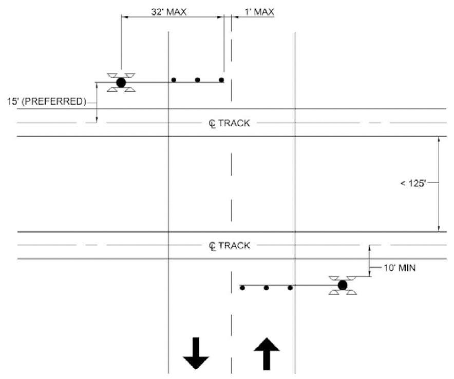
The lateral location of flashing light and gate assemblies should provide adequate clearance from the track as well as space for construction of the foundations. (The area for the foundation and excavation should be analyzed to determine the effect on sidewalks, utility facilities, and drainage.) Figure 27 indicates current standards: It should be noted that commercially available components may encroach on the desired 10-foot clearance between the face of the device and center of rail, therefore a 12-foot setback may be inadequate. For these reasons, some railroads require a 15-foot minimum clearance.
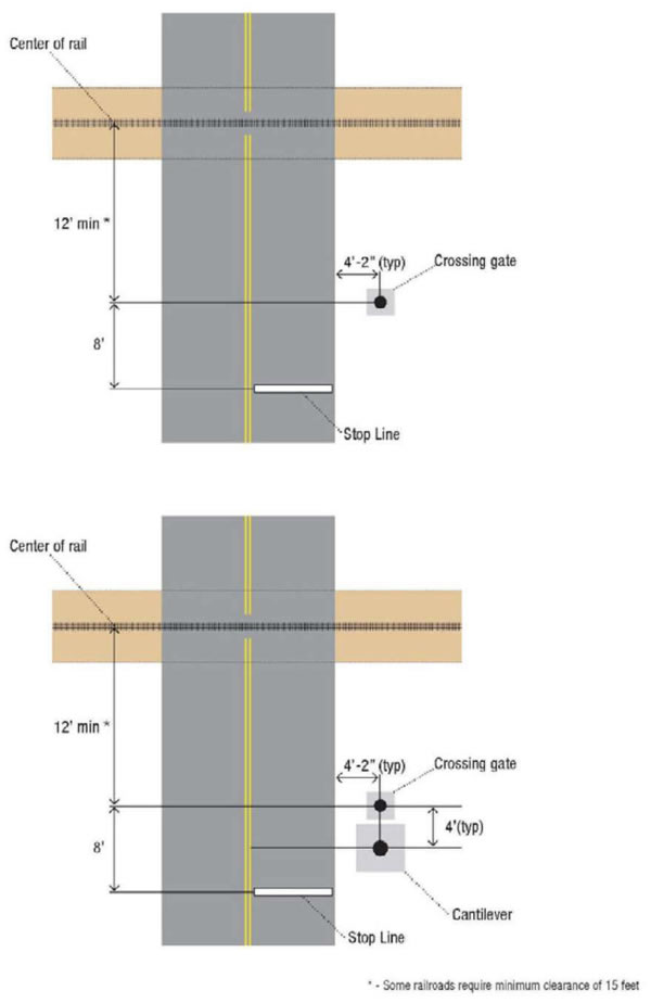
Source: Institute of Transportation Engineers.
If it is necessary to locate the supporting post in a potentially hazardous position to ensure adequate visibility, some type of safety barrier should be considered. These are discussed in a later section.
Large multilane intersections and intersections with unusual configurations should be carefully studied to determine the appropriate layout of crossing gate locations. For such conditions, gate arm requirements may become a principal factor in the layout of the intersection geometry and channelization from the outset. The crossing gate (and, therefore, traffic control) treatment should be an integral part of the design of an intersection, not an afterthought.
Discussion on pedestrian treatments can be found in the Pedestrian Treatments section of this document.
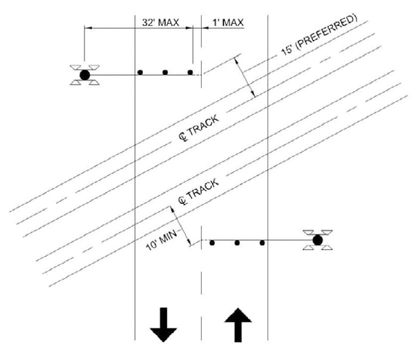
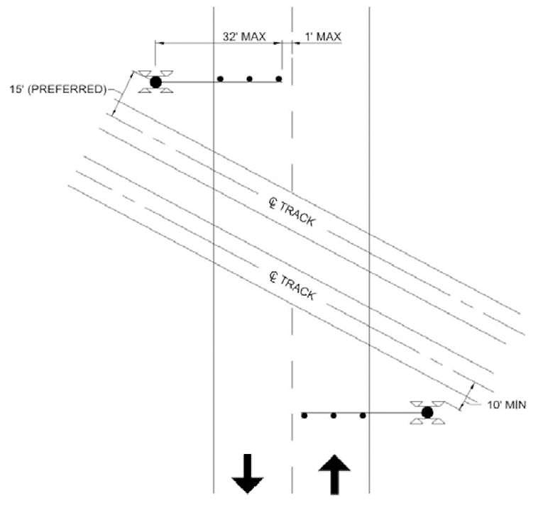
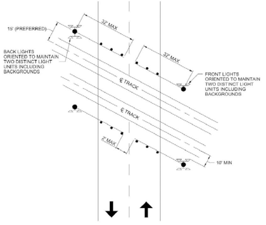
It is desirable to place crossing gates perpendicular to the direction of travel on the approach roadway. Figure 28 provides an illustrative example for an orthogonal crossing. The crossing gate mast should be 15 feet from the center of rail; where necessary, this distance can be reduced with concurrence from the railroad provided a minimum distance of 10 feet from the center of rail to the face of any part of the device is maintained. The crossing gate arm typically has a maximum length of 32 feet; if allowed by the railroad, longer gate arms may be used. At locations where the crossing is at a skew angle, the crossing gates need to be set back to be installed perpendicular to the roadway while meeting the required minimum 12-foot distance from the center of rail (refer to Figure 29 and Figure 30 for obtuse and acute angled crossings, respectively). At locations where there is a frontage road intersection close to the crossing, it may not be possible to achieve a mounting perpendicular to the approach roadway and angling the crossing gates may be required as shown in Figure 31. Angled crossing gates reduce the size of the zone between the crossing gate and rail, and may be helpful to prevent vehicles from driving around the entry gates. Current retroreflective materials are activated over a very wide angle and should be visible at night; rotating the gates minimizes the area behind the gate and results in a shorter pedestrian zone behind the gates.
Multi-lane highways typically require use of median-mounted crossing gates. A median-mounted gate may satisfy the criteria to have one set of flashing-light devices aimed at each approach lane. If there are three or more approach lanes, a cantilever is usually required. Examples showing use of medians with median gates and with the cantilever mounted upstream and downstream from the crossing gates are shown in Figure 32 and Figure 33, respectively.
Refer to the subsequent topic Use of Channelization with Gates for more information on median treatments.
Source: Institute of Transportation Engineers.
Source: Institute of Transportation Engineers.
Source: Institute of Transportation Engineers.
(Shown with Exit Gates)
Source: Institute of Transportation Engineers.
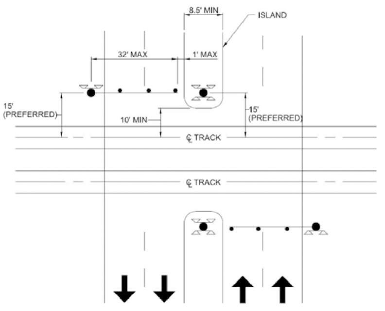
Source: Institute of Transportation Engineers.
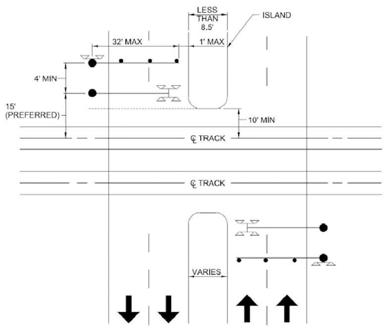
Figure 33. Typical Crossing Gate and Cantilever Placement at Multi-Lane Roadway with Medians and Median Gates–Cantilever Downstream from Gates
Source: Institute of Transportation Engineers.
Four-Quadrant Gates
Four-quadrant gate1 systems consist of a series of automatic flashing-light signals and gates in which the gates extend across all roadway lanes on both the approach and the departure side of the crossing. Unlike two-quadrant gate systems, four-quadrant gates provide additional visual constraints and inhibit most traffic movements over the crossing after the gates have been lowered.
The use of four-quadrant gates has increased significantly in the past decade for two main reasons: (1) design criteria adopted by transit and commuter rail operators which requires use of gates on all crossing approaches, and (2) "Quiet Zones" where four-quadrant gates have been used for risk reduction.
There are two recognized methods for operation of the exit gates: timed or dynamic. In the first instance, exit gates operate on a delay timer to allow vehicles which pass by the entry gates to exit the crossing zone before the exit gates are lowered. In the second case, known as "dynamic exit gate operating mode," an "exit gate management system" with detection loops in the crossing area is used to monitor vehicle presence within the crossing and hold open and/or raise the exit gates if vehicles are on the crossing after the entry gates are lowered. This second method is costlier to install and maintain but may be preferred at locations where the traffic flow rate is unpredictable to assure exit gates do not descend on vehicles. On the other hand, it is possible for a vehicle to back up into the vicinity of an exit gate loop and cause the gate to raise. It should be noted that some jurisdictions may require use of the dynamic operating mode by policy.2
Entry gates are designed to "fail-safe in the down position" (e.g., they are powered up and if the power fails, they will lower by gravity). However, the failure mode for exit gates is to "fail-safe in the up position" so that vehicles do not become trapped on the crossing in the event of a power failure. Additional guidance for Four-Quadrant Gate Systems operation can be found in MUTCD Section 8C.06.
Four-quadrant gates are recognized as a "Supplemental Safety Measure" (SSM) in FRA regulations governing Quiet Zones (49 CFR Part 222, Appendix A). It should be noted that FRA has assigned a lower effectiveness rate to installations that include vehicle presence detection because the act of raising the exit gates may allow vehicles to enter the crossing. Figure 34 shows four quadrant gate treatments for various conditions.
1 Because of varying intersection configurations, not all crossings using exit gates have gates in all four quadrants; the term "Full Closure" is a broader characterization of crossings with gates to block exit lanes.
2 For example, the California Public Utilities Commission (CPUC) requires use of a vehicle presence system "subject to a Commission staff diagnostic field meeting recommendation and an engineering study performed by railroad or local agencies" (General Order 75-D).
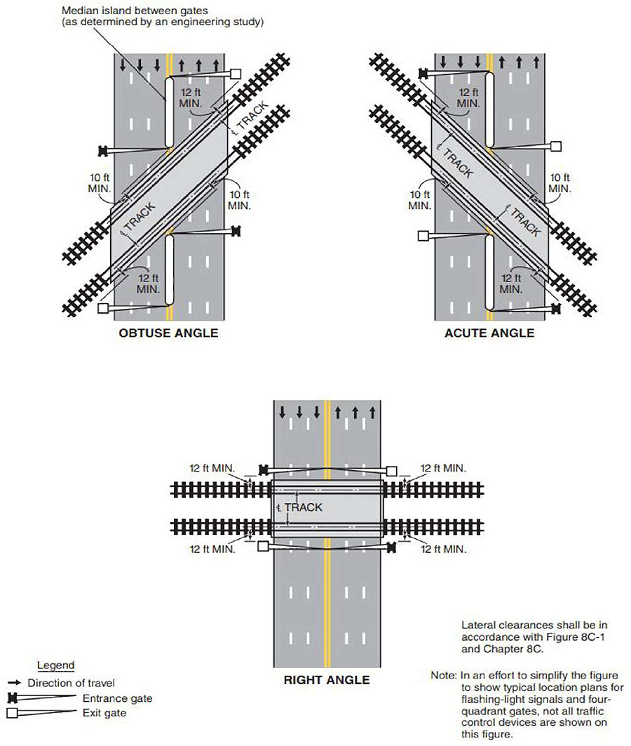
Source: Manual on Uniform Traffic Control Devices, 2009 Edition, Figure 8C-2, Washington, DC, FHWA, 2009.
Barrier Gate
The barrier gate is a movable automatic gate designed to close an approaching roadway temporarily at a highway-rail crossing (see Figure 35). A typical installation includes a housing containing electromechanical components that lower and raise the gate arm, the arm itself, and a locking assembly bolted to a concrete foundation to receive and hold the lowered gate arm in place. The barrier gate arm has been installed with a system consisting of three steel cables, the top and bottom of which are enclosed aluminum tubes.

Source: B&B Roadway–Resistance Barrier. (n.d.). Retrieved July 17, 2018, from https://bbrss.com/product/vt-6802hdtr/
Barrier devices should at least meet the evaluation criteria for a MASH(24) attenuator; stopping an empty 4,500-pound pickup truck traveling at 43 mph. Barrier gates have been tested to safely stop a pick-up truck traveling at 45 mph.
Barrier gates could be applied to situations requiring a positive barrier, such as closing-off road traffic and opening crossings only on demand. FRA regulations(7) also require use of FRA-approved barrier and/or enhanced warning systems for train operation over 110 mph. FRA has indicated that a barrier gate, if equipped with monitoring device, may be used to enforce a nighttime closure for partial quiet zones.
