
NEW CROSSINGS
Like crossing closure/consolidation, opening a new public highway-rail crossing should likewise consider public safety, necessity, access, and economics. Generally, new crossings (particularly on mainline tracks) should not be permitted unless no other viable alternatives exist. Even in those instances, consideration should be given to closing one or more existing crossings.
Communities, developers, and highway transportation planners need to be mindful that once a highway-rail crossing is established, drivers can develop a low tolerance for the crossing if blocked by a train for an extended period. If a new access is proposed to cross a railroad where railroad operation requires temporarily holding trains, only grade separation should be considered.
PASSIVE CROSSING TREATMENTS
Passive traffic control devices consist of regulatory signs, warning signs, guide signs, and pavement markings. These devices provide static messages of warning, guidance, and in some instances, mandatory action for the driver. Their purpose is to identify and direct attention to the location of a crossing to permit drivers and pedestrians to take appropriate action. Passive devices may be used at a passive crossing or may be used in conjunction with active devices at an active crossing. (Refer to the Sight Distance section for a discussion of sight distance requirements for passive crossings.)
Signs and pavement markings are to be in conformance with the MUTCD. New editions of the MUTCD are released periodically. Between MUTCD updates, the FHWA provides official interpretations, manages traffic control device experimentations, and issues interim approvals for new traffic control devices. Practitioners should confirm all signs, dimensions, and criteria with the latest edition of MUTCD.
Signs
Part 8 of the MUTCD includes provisions for use of signs at crossings and contains two figures which provide "sign panels" depicting regulatory and warning signs which are most relevant to crossings (MUTCD Figures 8B-1 and 8B-4). Some of these signs are in general use; others are specific to crossings.
Figure 7 depicts the regulatory sign panel. The "Crossbuck" sign (R15-1) is required to be used on each highway approach to every crossing, alone or in combination with other devices with a minor exception for LRT crossings where its use is optional in semi-exclusive or mixed-use alignments. At passive crossings, the Crossbuck sign is used within a "Crossbuck Assembly" in conjunction with use of a STOP or YIELD sign as further described below. Many of the other regulatory signs such as the NO RIGHT (LEFT) TURN ACROSS TRACKS (R3-1a/R3-2a) blank-out signs, the DO NOT STOP ON TRACKS (R8-8), and the "Stop Here" series (R8-10/10a) and R10-6/6a) signs are used in conjunction with active devices. The signs in the fourth row are for use with LRT or street-running rail.

Source: Manual on Uniform Traffic Control Devices, 2009 Edition. Figure 8B-1 Regulatory Signs and Plaques for Grade Crossings, Washington, DC, FHWA, 2009.
Figure 8 shows the warning sign panel. Part 8 of the MUTCD contains specific standards and guidance for the use of these signs. This section summarizes key requirements and gives examples for specific conditions for which these signs were intended to address.

Source: Manual on Uniform Traffic Control Devices, 2009 Edition, Figure 8B-4 Regulatory Signs and Plaques for Grade Crossings, Washington, DC, FHWA, 2009.
Table 4 lists all the signs which are included in Part 8 of the MUTCD along with a brief description of the intended application or indication of the need for each.
Table 4. Current MUTCD Signs
| Sign Designation | Section | Sign or Plaque | Application or Indication of Need |
|---|---|---|---|
| R3-1 | 8B.08 | No Right Turn | Movement Prohibition |
| R3-2 | 8B.08 | No Left Turn | Movement Prohibition |
| R1-1 | 8B.04, 8B.05 | STOP | Standard–A STOP or YIELD sign is required to be used as part of a Crossbuck Assembly at passive crossings (refer to text for specifics). |
| R1-2 | 8B.04, 8B.05 | YIELD | Standard–A STOP or YIELD sign is required to be used as part of a Crossbuck Assembly at passive crossings (refer to text for specifics). |
| R8-8 | 8B.09 | Do Not Stop on Tracks | Should be used where an engineering study indicates the potential for vehicles to stop on the crossing is significant. |
| R8-9 | 8A.05, 8B.10 | Tracks Out of Service | May be used with engineering judgement as a temporary provision before tracks will be removed or paved over. |
| R8-10, 10a | 8B.11 | Stop Here When Flashing | May be used at a highway-rail crossing to inform drivers of the location of the stop line or the point at which to stop when the flashing-light signals (Section 8C.02) are activated. |
| R10-6, 6a | 8B.12, 8C.09 | Stop Here on Red | May be used at locations where vehicles frequently violate the stop line or where it is not obvious to road users where to stop. |
| R10-11a | 8B.08, 8C.09 | No Turn on Red | May be used in conjunction with preemption of a traffic signal to prohibit turning movements toward the tracks (refer to text on preemption). |
| R15-1 | 5F.02, 8B.03, 8B.04, 8B.10, 8C.02, 8C.13, | Grade Crossing (Crossbuck) | Standard–Required as part of a Crossbuck Assembly with limited exceptions (refer to text for specifics). |
| R15-2P | 5F.02, 8B.03, 8B.04, 8B.10, 8C.02, 9B.14 | Number of Tracks | Standard–Required as part of a Crossbuck Assembly at locations with two or more tracks and no gate; optional with gate. |
| R15-3P | 8B.07 | Exempt | Recommended where school buses and commercial vehicles that are usually required to stop at crossings are not required to do so where authorized by ordinance. |
| R15-4a | 8B.13 | Light Rail Only Right Lane | May be used for multilane operations where roadway users might need additional guidance on lane use and/or restrictions. |
| R15-4b | 8B.13 | Light Rail Only Left Lane | May be used for multilane operations where roadway users might need additional guidance on lane use and/or restrictions. |
| R15-4c | 8B.13 | Light Rail Only Center Lane | May be used for multilane operations where roadway users might need additional guidance on lane use and/or restrictions. |
| R15-5 | 8B.14 | Light Rail Do Not Pass | May be used where vehicles are not allowed to pass LRT vehicles that are loading or unloading passengers at locations where no raised platform physically separates the lanes. |
| R15-5a | 8B.14 | Do Not Pass Stopped Train | Same as R15-5. |
| R15-6 | 8B.15 | Do Not Drive On Tracks Light Rail Symbol | May be used where there are adjacent vehicle lanes separated from the LRT track only by a curb or pavement markings. |
| R15-6a | 8B.15 | Do Not Drive On Tracks | Same as R15-6. |
| R15-7 | 8B.16 | Light Rail Divided Highway Symbol | May be used with appropriate geometric conditions. |
| R15-7a | 8B.16 | Light Rail Divided Highway Symbol (T-intersection) | Same as R15-7. |
| R15-8 | 8B.17, 8C.13 | Look | May be used to advise pedestrians to anticipate a train or LRV coming from either direction. |
| W10-1 | 8B.06, 8B.25 | Grade Crossing Advance Warning | Standard–Required device, with MUTCD exceptions (Section 8B.06). |
| W10-1aP | 8B.07 | Exempt | Should be used with W10-1 at Exempt locations (refer to R15-3P). |
| W10-2,3,4 | 8B.06, 5F.03 | Highway-Rail Grade Crossing Advance Warning | Required on parallel roadways where there is an intersection within 100 feet of a crossing (refer to text for specifics). |
| W10-5, W10-5P | 8B.23 | Low Ground Clearance Highway-Rail Grade Crossing | Should be used as indicated by MUTCD guidelines, incident history, or local knowledge. |
| W10-7 | 8B.19 | Light Rail Activated Blank-Out Symbol | May be used to warn road users of an approaching LRT vehicle. |
| W10-8 | 8B.20 | Trains May Exceed 80 mph | Should be used where train speed is 80 mph or faster. |
| W10-9, W10-9P | 8B.21, 9B.19 | No Train Horn | Required at crossings in FRA-authorized quiet zones. |
| W10-11 | 8B.24 | Storage Space Symbol | Should be used where there is inadequate clear storage space between the crossing and a downstream intersection, as determined by engineering study. |
| W10-11a | 8B.24 | Storage Space XX Feet Between Tracks and Highway | Should be used in conjunction with W10-11. |
| W10-11b | 8B.24 | Storage Space XX Feet Between Highway Tracks Behind You | May be used in conjunction with W10-11. |
| W10-12 | 8B.25, 9B.19 | Skewed Crossing | May be used at a skewed highway-rail crossing to warn drivers that the railroad tracks are not perpendicular to the highway. |
| W10-13P | 8B.22 | No Gates or Lights | May be installed at highway-rail crossings that are not equipped with active warning devices. |
| W10-14P | 8B.23 | Next Crossing | May be used in conjunction with other warning signs to advise drivers of alternate route. |
| W10-14aP | 8B.23 | Use Next Crossing | Refer to W10-14P. |
| W10-15P | 8B.23 | Rough Crossing | May be used if the highway-rail crossing is rough. |
| I-13 | 8B.8 | Emergency Notification | Should be installed at all crossings to provide for emergency notification. |
Source: Adapted from Manual on Uniform Traffic Control Devices, 2009 Edition. FHWA, Washington, DC, 2009.
The MUTCD Section 2A.16 (Standardization of Location) discusses Standards and Guidance for positions and locations of signage. In general, MUTCD specifies that signs should be located on the right-hand side of the highway, where the driver is looking for them. Signs should be located to optimize visibility. Signs should not be in a highway dip or beyond the crest of a hill. Care should be taken so that the sign is not obscured by parked cars or foliage or covered by roadside splatter or snow accumulation.
Section 8A.04 of the MUTCD discusses the importance of retroreflective or illuminated signs and object markers to meet requirements both by day and by night. MUTCD Section 2A.15 contains a wide range of provisions for increasing sign conspicuity including the use of LED enhancement. Section 2A.07 contains general provisions for retroreflectivity and illumination; signs may be "flashed" in accordance with flash rates specified in this section. Conditions under which enhancement may be desired include the following:
- Locations with visual clutter due to a combination of existing traffic control signs and adjacent commercial signs
- Locations where the horizontal and/or vertical alignment of the approach roadway in combination with sign placement requirements reduce sign visibility
- Locations where observation indicates low compliance with posted signs
"GRADE CROSSING" (Crossbuck) sign (R15-1) and "NUMBER OF TRACKS" sign (R15-2): The "GRADE CROSSING" sign, commonly identified as the "Crossbuck" consists of a white reflectorized background with the words "RAILROAD CROSSING" in black lettering, as shown in Figure 9. Per Section 8B.03 of the MUTCD, the use of the Crossbuck sign at all highway-rail crossings is considered standard practice. The only exception to this requirement is for LRT crossings, where use of the Crossbuck is optional. The MUTCD requires use of the Crossbuck sign, along with the "NUMBER OF TRACKS" sign (where more than one track is present) on each approach to a public highway-rail crossing. The railroad Crossbuck sign and other supplemental signs attached to the Crossbuck mast are usually installed and maintained by the railroad company. (The agency responsible for maintenance of the roadway is normally responsible for advance warning signs and pavement markings.)
Crossbuck signs should be located with respect to the highway pavement or shoulder as discussed above for all signs and should be located with respect to the nearest track in accordance with signal locations as discussed in the next section. Where unusual conditions exist, the placement of Crossbucks should provide the best combination of view and safety clearances as determined by engineering judgment.
Crossbuck Assembly: For passive crossings, the Crossbuck sign is incorporated in a Crossbuck Assembly which includes, the "NUMBER OF TRACKS" sign (required if there is more than one track), and either a "YIELD" or "STOP" sign, with "YIELD" being the default sign subject to engineering study. (Where applicable, each State's MUTCD supplements to these treatments should be considered.) Figure 11 and Figure 12 illustrate the Crossbuck Assembly, showing the different sign selections and orientations that are possible, as shown in Chapter 8B in the MUTCD. Figure 10 shows the typical layout on the approach to a crossing.
The following standards and/or guidance can be considered for the installation of YIELD or STOP signs at passive crossings per the MUTCD:
- When the YIELD or STOP sign is installed on the same support as the Crossbuck sign, a strip of retroreflective material shall be used on the front and back of the support. The color of the retroreflective strip on the front of the support may be red or white (as per MUTCD Figure 8B-2). The color of the retroreflective strip on the back of the support shall be white. The dimensions and placement of the retroreflective strips should be in conformance with the standards in Section 8B.04.
- When the YIELD or STOP sign is installed on a separate support, a retroreflective strip of red may be installed on the front of the post. The separate Crossbuck support shall have a white strip post front and back (see MUTCD 8B-3).
- When a STOP sign is installed in conjunction with the Crossbuck sign, a stop line should be installed, if appropriate to the roadway surface, to indicate the point behind which vehicles are required to stop, as per MUTCD Section 8B.28.
- When a YIELD sign is used in conjunction with the Crossbuck sign, either a yield line (per MUTCD Section 3B.16) or a stop line (per MUTCD Section 8B.28 and Figure 8B-6) may be installed to indicate the point behind which vehicles are required to yield or stop. When used, the stop line or yield line (such as size, pattern, and location) must be in conformance with provisions in Part 3 of the current edition of MUTCD).

Source: Manual on Uniform Traffic Control Devices, 2009 Edition, Figure R15-1, Washington, DC, FHWA, 2009.
Source: Traffic Control Devices Handbook, Washington, DC, ITE, 2013.

Source: Manual on Uniform Traffic Control Devices 2009 Edition, Figure 8B-2, Washington, DC, FHWA, 2009.

Source: Manual on Uniform Traffic Control Devices 2009 Edition, Figure 8B-3, STOP sign panel, Washington, DC, FHWA, 2009.
Emergency Notification sign (I-13): Except for crossings located within railroad yards or port and dock facilities, FRA regulations (49 CFR 234.311) require the installation of Emergency Notification System signs at highway-rail and pathway grade crossings to provide information to road users so that they can notify the railroad company about unsafe conditions or malfunctioning active crossing warning devices. Figure 13 shows an example of this sign, which is an approved alternate to the Emergency Notification (I-13) sign shown in Figure 8B-5 of the MUTCD.
Advance Warning Signs (Wl0-1, Wl0-2, Wl0-3, W10-4): The round, black, and yellow advance warning sign (W10-1) is located in advance of the crossings and serves to alert the motorist that a crossing is ahead. The advance warning sign has a minimum diameter of 36 inches for conventional roads. Per the MUTCD, the sign is required in advance of all crossings except the following:
- On an approach to a highway-rail crossing from a T-intersection with a parallel highway, if the distance from the edge of the track to the edge of the parallel roadway is less than 100 feet and W10-3 signs are used on both approaches of the parallel highway
- On low-volume, low-speed highways crossing minor spurs or other tracks that are infrequently used and are flagged by train crews
- In business districts where active highway-rail crossing traffic control devices are in use
- Where physical conditions do not permit even a partially effective display of the sign
When the crossing is on a divided highway, it is desirable to place an additional advance warning sign on the left side of each approach. It may also be desirable to place an additional sign on the left side of a highway approach when the highway alignment limits the visibility of signs mounted on the right side.
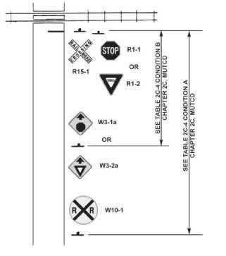
The distance from the advance warning sign to the track is dependent upon the highway speed, but in no case, should be less than 100 feet in advance of the nearest rail. This distance should allow the driver sufficient time to comprehend and react to the sign's message and to perform any necessary maneuver. (Table 2C-4 in the MUTCD provides recommended placement. Condition A is used for advanced warning sign placement.)
Where a road runs parallel to a railroad and the perpendicular distance between the two is less than 100 feet, there is not enough distance to display the advance warning sign (W10-1). For traffic turning from the parallel road, one of three other warning signs (W10-2, W10-3, and W10-4) can be used when their need has been determined from an engineering study (refer to Figure 14).
Storage Space signs (W10-11 & W10-11a): These signs should be used where there is a highway intersection near a crossing and there is not enough storage space to accommodate a design vehicle between the intersection and the dynamic envelope of a train or LRT, subject to an engineering study. Figure 15 provides an illustrative example of sign placements to address this condition.

Source: Standard Highway Signs: Including Pavement markings and Standard Alphabet, 2004 Edition, 2012 Supplement, Figure 8B-5. FHWA, Washington, DC, 2012.

Source: Geometric Design Criteria for Highway-Rail Intersections (Grade Crossings),
Washington, DC, ITE, 2001.

Source: Seyfried, R K., (Ed.), Traffic Control Devices Handbook 2nd Edition, Figure 11-3, Washington, DC, ITE, 2013.
Pavement Markings
Pavement markings are used to supplement the regulatory and warning messages presented by crossing signs and signals. Pavement markings have limitations in that they may be obliterated by snow, may not be visible when wet, and may not be very durable when subjected to heavy traffic.
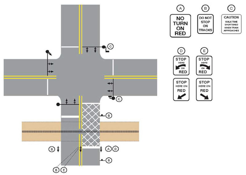
The MUTCD Section 8B.27 provides that on paved roadways, pavement markings in advance of highway-rail crossings shall consist of an X, the letters RR, a NO PASSING marking on two-lane, two-way highways with centerline markings, and certain transverse lines, as shown in Figure 16. Identical markings shall be placed in each approach lane on all paved approaches to crossings where crossing signals or automatic gates are located, and at all other crossings where the prevailing speed of highway traffic is 40 mph or greater. These markings are also to be placed at crossings where engineering studies indicate there is a significant potential conflict between vehicles and trains. These markings may be omitted at minor crossings or in urban areas if an engineering study indicates that other crossing devices provide suitable control. Figure 16 also shows a placement example of warning signs and pavement markings at highway-rail crossings.

Source: Manual on Uniform Traffic Control Devices 2009 Edition, Figure 8B-6, Washington, DC, FHWA, 2009.
The MUTCD requires that pavement markings specific to crossings shall be retroreflectorized. Other markings are required to comply with MUTCD provisions in Part 3 which requires use of retroreflective materials and/or illumination unless ambient illumination provides adequate night time visibility. Raised pavement markers can be used to supplement pavement markings in advance of crossings. The longitudinal lines, "X" symbol, and stop line can be delineated by raised retroreflective markers to provide improved guidance at night and during periods of rain and fog. Disadvantages of raised pavement markers include the initial cost and the possibility of being damaged or removed by snow plows.
The MUTCD recommends all pavement markings be retroreflectorized white except for the NO PASSING markings that are to be retroreflectorized yellow. By this standard, the stop line is to be 2 feet in width and extend across the approach lanes, and the stop line should be located perpendicular to the highway centerline and approximately 15 feet from the nearest rail. Where automatic gates are installed, the stop line should be located approximately 8 feet in advance of where the gate arm crosses the highway surface.
Exclusion Zone (Keep Clear) Treatments
At locations where queueing on the tracks is of concern due to limited storage space downstream from the crossing, Do Not Block Intersection markings may be used to mark the edges of an intersection area that is in close proximity to a railroad crossing per MUTCD Section 3B.17. Options for the design of Do Not Block Intersection pavement markings are provided in MUTCD Figure 3B-18.
The Illinois DOT design standard uses cross-hatching at pre-signal locations as presented in its design manual and supporting traffic control design standards, as shown in Figure 17.
Edge Lines
Widespread use of Global Positioning System (GPS) navigational guidance has been identified as a causative factor in collisions where road users inadvertently turned onto the tracks ahead of a highway intersection at night.(27) Carrying edge lines and centerlines across the tracks and careful placement of arrow markings can reduce the likelihood of this type of collision.
Channelizing devices such as tubular markers can be used in conjunction with edge lines at locations where the alignment curves or in rural locations to guide users safely through crossings. Refer to MUTCD Section 3F. Figure 18 shows a typical treatment.
Source: Adapted from Signing and Pavement Marking at Railroad Crossings Memorandum, Typical Supplemental Sign Pavement Marking for Railroad Crossing, IDOTDistrict 1, April 8, 2014.

Source: Google Earth.
Arrow Markings
Where pavement arrow markings are needed, current practice is to place arrow markings 100 feet or more in advance of the stop line. Practitioners are advised to avoid placement of pavement arrows immediately in advance of the tracks; it may be necessary to place two sets of markings, one between the crossing and the downstream highway and another set well in advance of the crossing, if practicable.
Dynamic Envelope
The dynamic envelope, see Figure 19, is the region between and immediately adjacent to the tracks at a crossing where a road user could be struck by a train considering equipment sway. This zone may be delineated with four-inch white pavement markings or other means as described in MUTCD 8B.29.

Source: Manual on Uniform Traffic Control Devices 2009 Edition, Figure 8B-8, Washington, DC, FHWA, 2009.
The dynamic envelope is specific to the type of rail equipment, which may be operated on the tracks, e.g., the dynamic envelope for freight rail differs from the dynamic envelope for LRT trains. The dynamic envelope is a clearance envelope which considers not only the size and shape of the rail vehicles, but also the overhang and sway of the vehicles moving along the tracks and around curves. The Association of American Railroads (AAR) indicates 10 feet-8 inches as a standard width of the dynamic envelope, so marking the dynamic envelope just beyond 3 feet from the rail is a current practice applicable to freight rail.