CHAPTER 4. SIGNS
There are several signing options that road agencies should consider installing at a horizontal curve, especially curves with attributes that data or experience identify as potentially problematic.
Agencies should apply signing devices uniformly, based on the sharpness of the curve. This uniformity provides drivers with a consistent message on which to base their expectations. The MUTCD provides specific recommendations and requirements for uniform application of many of these basic devices. The MUTCD requires that the use of warning signs shall be based on an engineering study or engineering judgment. Factors to consider include:
- The difference between the posted speed limit and recommended advisory speed.
- Geometric features of the curve to include its length, radius, shoulders and roadside features.
- Unexpected geometric features within the curve, such as an intersection, change in grade, change in curve radius, or visual cues that contradict the roadway alignment.
- A sudden change in alignment after many miles of consistently straight roadway.
- Traffic volume.
- Crash data.
Many curves need only the basic horizontal alignment warning signs. The decision to add one or more of the other basic or enhanced treatments at a specific curve will be influenced by the factors noted above, but should be prefaced by an assessment at the system and corridor level. The assessment may reveal unnecessary devices that should be removed, improperly placed devices that should be moved, or required or recommended devices that are missing. Providing uniformity may be all that is necessary to address an identified safety concern. If the problem is not resolved by using a uniform application, then additional devices should be considered.
The following discussion provides a summary of basic and enhanced signage, followed by a discussion on maintenance considerations applicable to signs. All example signs are from the MUTCD.
BASIC SIGNING COUNTERMEASURES
Advance Warning Signs
Warning signs call attention to unexpected conditions on or adjacent to a roadway. The MUTCD prescribes several Horizontal Alignment signs to give drivers advance warning of a horizontal curve, as illustrated in Figure 20.
For a single curve section, use one of these four signs in advance of the curve:
- Turn (W1-1).
- Curve (W1-2).
- Hairpin Curve (W1-11).
- 270-degree Loop (W1-15).
For sections with more than one curve in close proximity, use one of these three warning signs in advance of the first curve:
- Reverse Turn (W1-3).
- Reverse Curve (W1-4).
- Winding Road (W1-5).

Figure 20. Illustration. Figure 2C-1 from the MUTCD.
Design and Application
The MUTCD requires the use of a warning sign be based on an engineering study or engineering judgment, but the MUTCD also has specific requirements for warning signs based on traffic volume and curvature. For freeways, expressways, and roadways with more than 1,000 AADT that are functionally classified as arterials or collectors, refer to Table 2C-5 from the 2009 MUTCD (shown in Table 4) to determine those signs that are required or recommended for use based on the difference in posted speed limit and advisory speed. This table provides uniform guidelines for placement of not only advance warning signs but also chevrons, which provide a consistent message to the driver if applied uniformly. The criteria in Table 2C-5 may also be used for local roads and those with less than 1,000 ADT, based on engineering judgment. Warning signs sizes should follow MUTCD Tables 2C-2 and 2C-3, and the signs should be located per Table 2C-4 (MUTCD, Section 2C). Further information on design and application is discussed under the individual devices.
Table 4. Horizontal Alignment Sign Selection (MUTCD Table 2C-5 Excerpt).
| Type of Horizontal Alignment Sign |
Difference Between Speed Limit and Advisory Speed |
||||
|---|---|---|---|---|---|
| 5 mph | 10 mph | 15 mph | 20 mph | 25 mph or more | |
|
Recommended | Required | Required | Required | Required |
|
Recommended | Required | Required | Required | Required |
|
Optional | Recommended | Required | Required | Required |
Note: "Required" indicates that the sign and/or plaque shall be used, "Recommended" indicates that the sign and/or plaque should be used, and "Optional" means that the sign and/or plaque may be used.
For horizontal curves where a Horizontal Alignment sign is not required or recommended, engineering judgment should be applied to determine whether a sign is needed. For instance, a roadway with center line and edge line pavement markings, where the alignment change is not unexpected and where there is no crash history, may not need a sign. For those curves that do need advance warning signs, use the Curve sign unless the advisory speed is 30 mph or less, in which case the Turn sign is required. Use the Hairpin Curve sign when the change in horizontal alignment is 135 degrees or more. The Loop sign indicates a change of approximately 270 degrees in direction, such as cloverleaf interchange ramps, and is not addressed in this publication.
The two sequential curves signs (left turning followed by right turning or vice versa) are Reverse Turn (W1-3) and Reverse Curve (W1-4). These should be used when the tangent distance between the two curves is less than 600 feet. The guidance on which one to use is the same for selecting a Turn or Curve sign and agencies should base their decision on the advisory speed, as with the single Turn and Curve signs. For road segments with three or more alignment changes in opposite directions in relatively close proximity, the Winding Road (W1-5) sign may be used.
Depending on the geometry of the curve or sets of curves, place the appropriate sign the distance in advance of the point of curvature, as shown in MUTCD Table 2 C-4 presented in Chapter 3. This type of sign, and others discussed in this publication, should be located as described in MUTCD Section 2A.16.
Materials
Traffic signs of all types use retroreflective sheeting to ensure they are visible to drivers at night or in periods of low light. In the interest of improved visibility and sign life, many agencies have transitioned from using engineering grade to high-intensity grade and even prismatic sheeting. Information regarding various available sheeting types can be found in the Traffic Sign Retroreflective Sheeting Identification Guide. Higher grades generally can be seen from a further distance and typically last longer.
Effectiveness
The CMF Clearinghouse lists two "advance static curve warning signs" countermeasures, which report a 30-percent decrease in all minor and serious injury crashes (CMF is 1 star) (Elvik and Vaa, 2004) and an 8-percent decrease in all property damage only (PDO) crashes (CMF is 1 star) (Elvik and Vaa, 2004). However, both of these countermeasures received a rating of only one star, indicating the quality or confidence in the results of the study is not reliable.
Relative Cost
This countermeasure is low cost.
Advisory Speed Plaque
An Advisory Speed plaque (W13-1P) is a sign placed below a Horizontal Alignment sign (discussed in previous section) to advise motorists of the safe speed through the curve(s). It does not indicate the legal speed limit. Figure 21 shows an example of an advisory speed plaque.
Design and Application
The MUTCD requires an advisory speed plaque when an engineering study indicates a need. It is also required for roadways with more than 1,000 ADT whenever the difference between the advisory speed and the posted speed is 10 mph or greater and recommended at 5 mph difference in speeds according to Table 4. An engineering study is required to determine the appropriate advisory speed. The MUTCD outlines established practices that are appropriate for determining the recommended advisory speed for a horizontal curve that include an accelerometer, a design speed equation, or a 16-, 14-, or 12-degree ball bank indicator depending on the speed range.
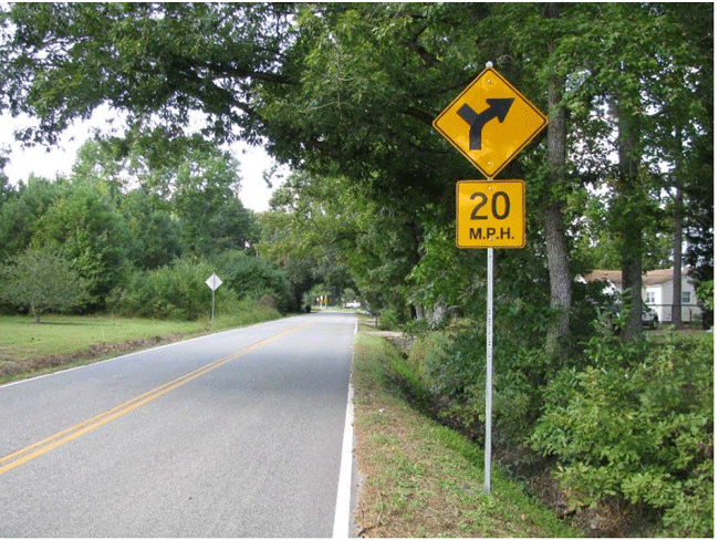
Figure 21. Photo. Advisory Speed Plaque.
See FHWA-SA-11-22, Procedure for Setting Advisory Speeds on Curves and the ITE Traffic Control Devices Handbook for additional methods of determining the advisory speed.
Effectiveness
The CMF Clearinghouse does not include any studies specifically for adding combination horizontal alignment/intersection warning signs along two-lane rural highway road segments.
Relative Cost
This countermeasure is low cost.
Combination Curve/Intersection Signs
An intersection near or within a curve adds another potential problem and more information for the driver to process. The combination Horizontal Alignment/Intersection sign (W1-10 Series) quickly communicates to the driver what to expect in advance.
The MUTCD states that turn arrows and reverse turn arrows may be substituted for the curve arrows and reverse curve arrows on the W1-10 series signs where appropriate (Figure 22).
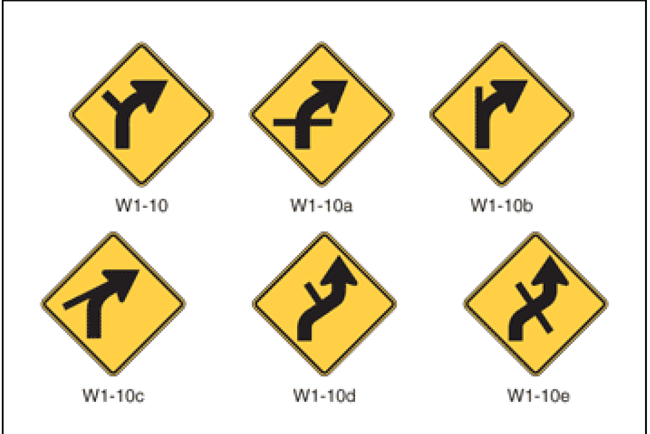
Figure 22. Illustration. Excerpt from Figure 2C-1 of the MUTCD.
Design and Application
The signs shown in Figure 22 are used in lieu of the horizontal alignment signs previously listed in Figure 20 and should comply with the provisions of both curve warning signs and with intersection warning signs. The symbol design should approximate the configuration of the intersecting roadway(s). However, no more than one Cross Road or two Side Road symbols should be displayed on any one combination Horizontal Alignment/Intersection sign.
The design and application of the combination Horizontal Alignment/Intersection sign is accordance with the appropriate Turn or Curve sign requirements.
Effectiveness
To date, no research has documented the safety effects of installing a combination horizontal alignment/intersection sign.
Relative Cost
This countermeasure is low cost.
SUPPLEMENTAL DEVICES IN A CURVE
Some curves will still violate driver expectancy with only advance warning signs. In those cases, additional traffic control devices used within the curve itself help guide motorists through the curve. These include combination curve/speed signs, chevrons, large arrow signs, and delineators.
Combination Horizontal Alignment/Advisory Speed Sign
When additional emphasis is needed to reduce speeds, agencies can add a combination Turn/Advisory Speed (W1-1a) sign or a combination Curve/Advisory Speed (W1-2a) sign. This sign is used as a supplement to–not a replacement for–the advance Horizontal Alignment sign and Advisory Speed plaque, and is placed at the beginning of the turn or curve (i.e., the point of curvature). The sign is intended to remind motorists of the need to slow down as they begin to negotiate the alignment change.
Design and Application
The MUTCD contains no guidance as to when to use these signs, so it is up to an agency's engineering judgment. It is probably best not to use it when the distance from the advance horizontal alignment sign and the point of curvature is 200 feet or less because the two signs would be too close together. The advisory speed on the combination Horizontal Alignment/Advisory Speed sign should be based on the advisory speed for the curve using recommended engineering practices.
Effectiveness
The HSM Table 13-30 shows a 13-percent decrease for injury crashes and 29-percent decrease for non-injury crashes associated with the installation of combination horizontal alignment/advisory speed sign (Elvik and Vaa, 2004). The CMF Clearinghouse lists the same CMFs with 3-star ratings, suggesting that the combined horizontal alignment/speed advisory sign safety effectiveness estimates are moderately reliable.
Relative Cost
This countermeasure is low cost.
Chevron Alignment Sign
Chevron Alignment (W1-8) signs emphasize and guide drivers through a change in horizontal alignment. Because of their pattern, size, and placement with at least two of the signs in view of the motorist, they define the direction and sharpness of the curve, the best of all the traffic control devices. When the chevron sign is used, agencies also need one of the advance curve warning signs previously discussed. Figures 23 and 24 illustrate a before and after installation.
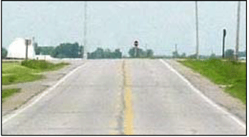
Figure 23. Photo. After, with chevrons. Chevrons provide advanced alignment of a curve.
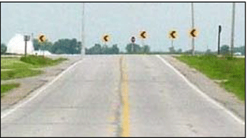
Figure 24. Photo. After, with chevrons. Chevrons provide advanced alignment of a curve.
Design and Application
Except on roads functionally classified as local or with volumes less than 1,000 ADT, the use of Chevron Alignment signs are to be in accordance with MUTCD Table 2C-5, which recommends use of chevrons where the difference between the advisory speed and posted speed is 10 mph, and requires their use when that difference is 15 mph or greater (see Table 4). Use at lower speed differences or on other roads is optional, based on engineering judgment. An agency may use chevrons instead of or in addition to standard delineators.
Chevrons are one of very few signs without a border, and are installed at a height of at least 4 feet above the roadway surface. Install a series of these signs on the outside of a turn or curve, positioned in line with approaching traffic at approximately a right angle to a driver's line of sight. On two-lane, two-way roads, use two-sided chevron signs properly aimed to guide traffic traveling both directions.
The spacing of the chevrons is measured from the point of curvature (PC) and should be as shown in the MUTCD Table 2C-6 (Table 5). The spacing is based on the advisory speed and radius of the curve. Figure 25 illustrates a layout of these devices on a curve with a retroreflective strip on the posts for increased conspicuity.
Table 5. Typical Spacing of Chevron Alignment Signs (MUTCD Table 2C-6).
| Advisory Speed | Curve Radius | Sign Spacing |
|---|---|---|
| 15 mph or less | Less than 200 feet | 40 feet |
| 20 to 30 mph | 200 to 400 feet | 80 feet |
| 35 to 45 mph | 401 to 700 feet | 120 feet |
| 50 to 60 mph | 701 to 1,250 feet | 160 feet |
| More than 60 mph | More than 1,250 feet | 200 feet |
Effectiveness
The CMF Clearinghouse lists a 4-percent to 25-percent reduction in crashes when chevrons are installed on rural highway curves (CMF is 4 stars) depending on the crash type (Srinivasan, 2009). There are even greater reductions when chevron installations are combined with advance curve warning signs and/or flashing beacons. In addition, according to NCHRP Report 559, chevrons have been shown to reduce vehicle encroachments onto the center line in curves where the degree of curvature is more than seven degrees (Lyles and Taylor, 2006).
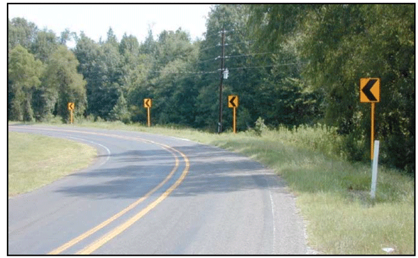
Figure 25. Photo. Chevrons assist the driver in navigating curves. Source: Texas Transportation Institute.
Relative Cost
This countermeasure is low cost.
The cost to apply chevrons to a curve will vary with the number of signs installed. It is not uncommon for one or more of the chevrons in problem curves to be periodically knocked down, so it is advisable for an agency to keep a supply of signs.
One-Direction Large Arrow Sign
The One-Direction Large Arrow sign (W1-6) is used to define a sharp change in horizontal alignment, as seen in Figure 26. Usually only one of these signs per direction is used for a horizontal curve or turn.
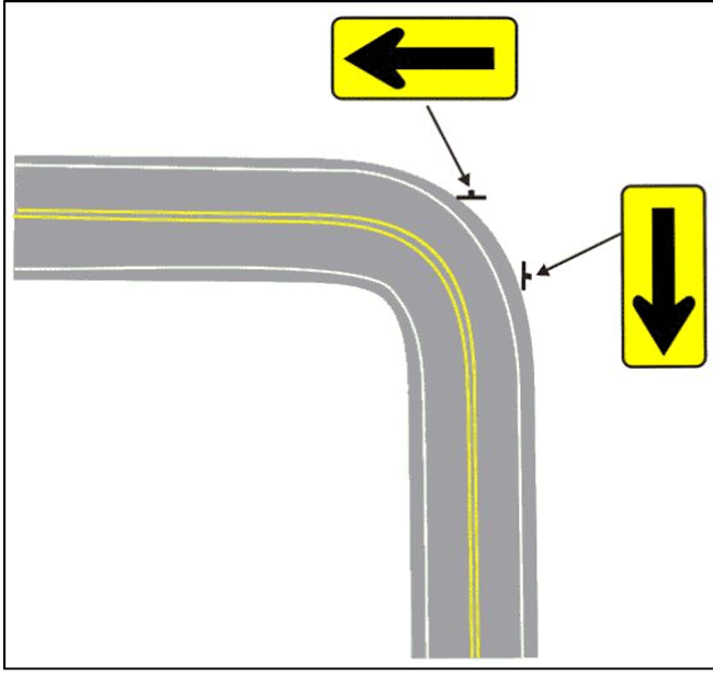
Figure 26. Illustration. Typical installation location of one-direction large arrow signs on a horizontal curve. Source: MoDOT Engineering Policy Guide.
Nothing in the MUTCD limits using multiple signs along the curve, but it may be more reasonable to use a series of Chevron (W1-8) signs. The Large Arrow sign is installed only on the outside of a turn or curve in line with, and at approximately a right angle to approaching traffic.
Design and Application
The Large Arrow sign may be used either as a supplement or alternative to Chevron signs in accordance with the information shown in Table 2C-5. If a Large Arrow sign is used with Chevron signs, it would take the place of a Chevron and not obstruct or be obstructed by a Chevron. Based on standard practice, this sign is limited to sharper curves (i.e., turns).
Effectiveness
To date there has been no research on the safety effectiveness of installing a large arrow sign, and therefore, it is not listed as a countermeasure by the CMF Clearinghouse.
Relative Cost
This countermeasure is low cost.
In 2010, the Ohio Department of Transportation introduced a Horizontal Curve Program which focused on upgrading and installing various signage at curves to address problematic locations. Individual districts conducted site field reviews, evaluated existing conditions and countermeasures onsite, and selected the appropriate signs to be installed at the site. Figure 27 shows a curve on a rural, two-lane road before signage updates and Figure 28 shows the same curve after signage updates through the Horizontal Curve Program. Images courtesy of Ohio DOT. See Appendix D for more information.
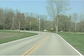
Figure 27. Photo. Before signage updates.
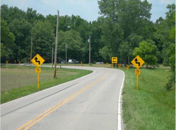
Figure 28. Photo. After signage updates.
ENHANCED SIGNING COUNTERMEASURES
Most basic devices described above can be improved in different ways to increase the number of drivers who perceive and react to them. The sooner a motorist is able to see a device and recognize its meaning, the more time there is to respond. The following enhanced signage countermeasures have proven effective in enhancing driver perception.
Larger Devices
The MUTCD prescribes the use of the "conventional road" sizes for typical situations. The minimum size is not recommended, but the MUTCD allows their use on low-speed roadways where the reduced letter size remains adequate for the warning or where physical conditions prevent using a larger size. The MUTCD also states that oversized and larger signs "…should be used for those special applications where speed, volume, or other factors result in conditions where increased emphasis, improved recognition, or increased legibility is needed, as determined by engineering judgment or study" (MUTCD, Section 2A.11). A horizontal curve identified for safety improvements would likely meet this condition.
Effectiveness
To date there has been no research documenting the safety effects of installing larger warning signs. Therefore, these signs are not listed as a countermeasure by the CMF Clearinghouse.
Relative Cost
This countermeasure is low cost.
Doubling-Up Devices
As seen in Figure 29, "doubling-up" simply refers to situations where agencies install a second, identical sign on the left side of the roadway. Agencies can do this for the basic signs discussed in this chapter. Doubling-up increases the opportunity for the motorist to see the sign, and respond to the message. Doubling-up is also a candidate countermeasure when visibility of the single right-hand side sign is less than desirable.
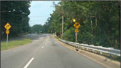
Figure 29. Photo. Doubling-up of the sign was used at this site because tree limbs partially blocked the right side sign.
Effectiveness
To date there has been no research documenting the safety effects of doubling-up curve warning signs, and therefore, it is not listed as a countermeasure by the CMF Clearinghouse.
Relative Cost
This countermeasure is low cost.
Retroreflective Strip on Sign Post
A strip of retroreflective material may be used on warning sign supports to draw more attention to the sign during nighttime conditions (MUTCD, Section 2A.21). If used, the strip of retroreflective material shall be at least 2 inches in width, placed along the full length of the sign support to within 2 feet of the roadway surface, and its color shall match the background color of the warning sign.
Effectiveness
To date there has been no research documenting the safety effects of installing a retroreflective strip on the posts of curve warning signs. However, a study from Iowa has shown that installing a retroreflective strip on chevron sign posts led to moderate reductions in the mean and 85th "percentile operating speeds along curves (Hallmark et al., 2012). This same study also indicated that there was a statistically significant reduction in the percentage of vehicles exceeding the posted speed limit by more than 10 mph.
Relative Cost
This countermeasure is low cost.
Highly Retroreflective and Fluorescent Sheeting
Another way to make signs more visible or more noticeable to motorists is to use highly retroreflective sheeting and fluorescent sheeting. As noted earlier in this chapter, the retroreflective sheeting for signs is available in different grades. Signs made with prismatic sheeting increase visibility from a longer distance at nighttime visibility. For more information on types of retroreflective sheeting, see Traffic Sign Retroreflective Sheeting identification Guide. Use of fluorescent yellow increases the visibility of warning signs, especially at dawn or dusk, as seen in Figure 30. This visual advantage works day and night.
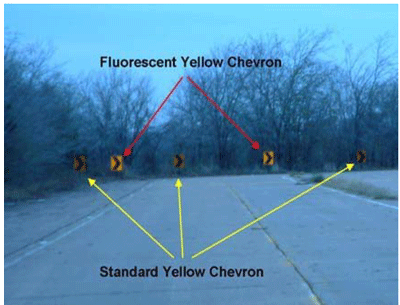
Figure 30. Photo. Stimulus photo illustrating enhanced chevron visibility. Source: Texas Transportation Institute.
Effectiveness
Initial research based on eye-tracking data indicates that upgrading conventional yellow chevrons to fluorescent yellow, while not affecting speed or lane placement, improves driver perception of the signs. This improved driver performance effect suggests a potential safety effect.
The CMF Clearinghouse lists an 18-percent to 35-percent reduction in various crash types on rural highways when new fluorescent curve signs are installed or existing curve signs are upgraded to fluorescent sheeting (Srinivasan et al., 2009). To date, no CMFs have been developed regarding improved retroreflectivity of signs.
Relative Cost
This countermeasure is low cost.
Flashing Beacons
Using flashing beacons with a warning sign is another way to gain motorists' attention, as seen in Figure 31. The beacons are typically used with one of the advance Horizontal Alignment signs for a horizontal curve. There are no published guidelines for when they are appropriate, but it is reasonable to limit them to locations where other countermeasures have not solved a safety problem. One factor limiting the use of beacons is the availability of an accessible power source, although agencies can use reliable solar power panel systems.
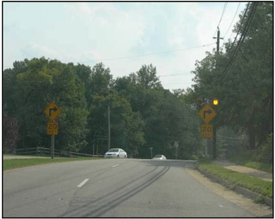
Figure 31. Photo. Typical arrangement of signs and flashing beacons.
The beacons used for this countermeasure are the circular yellow sections from a standard traffic signal. Agencies can install this with one or more beacons, but Figure 31 shows a typical arrangement. The beacons can be flashed either alternately or simultaneously. To prevent the flashing light from masking the sign message, locate the beacon signal housing at least 12 inches outside of the nearest edge of the sign.
Effectiveness
To date there has been no research documenting the safety effects of installing flashing beacons with warning signs, but when flashing beacons are installed in combination with curve warning signs and chevrons, the CMF Clearinghouse lists a 37-percent to 76-percent reduction in various crashes (CMFs are 3 stars) (Montella, 2009).
Relative Cost
This countermeasure is moderate cost.
Dynamic Curve Warning System
Agencies can enhance curve warning systems by using supplemental beacons and/or messages that activate when a motorist approaches the curve at a high speed. A typical dynamic curve warning system combines a speed measuring device (such as loop detectors or radar) with flashing beacon and a variable message sign. The system is designed to slow high-speed vehicles as they approach and enter a horizontal curve. It works by measuring the speeds of approaching vehicles and providing messages to speeding drivers to slow down to an advisory speed. Agencies can develop these systems using off-the-shelf technology. The advantage of this countermeasure is that the device has a much greater effect on high-speed vehicles than a static curve warning sign. A variety of these systems are deployed in the United States, as the examples in Figures 32 and 33 demonstrate.
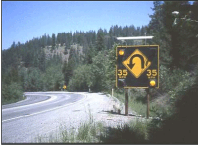
Figure 32. Photo. Speed Actuated Sign, Augusta, ME.
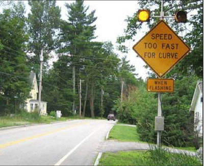
Figure 33. Photo. Flashing Beacon on Warning Sign, Augusta, ME.
Application
Because even the least expensive system is much more costly than static signs, agencies should limit their application to locations with high crash rates, especially those involving fatalities and injuries, and where other less expensive devices have failed to solve the problem.
One dynamic system application involves a radar speed detection device coupled with warning signs and activated flashing beacons. The Texas system, illustrated in Figures 34 and 35, advises drivers detected driving more than 5 mph over the 25-mph curve advisory speed limit to reduce their speed. A radar detector measures speeds and displays them using a speed display sign stating: "YOUR SPEED IS…" A W1-1 warning sign is located 625 feet in advance of the curve, and the overhead sign is located in the point of curvature. The radar is set to start processing the speed data about 300 feet before a vehicle reaches the overhead sign.
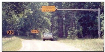
Figure 34. Photo. Texas System curve advisory speed limit sign. Camp County, Texas.
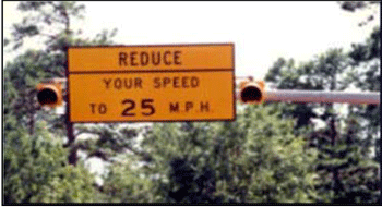
Figure 35. Photo. Texas System curve advisory speed limit sign. Camp County, Texas.
Effectiveness
A recently completed project by FHWA evaluated the effectiveness of low-cost, speed-activated dynamic curve warning systems on speeding and safety on horizontal curves in rural roadways. The study found a 5-percent (CMF is 5 stars) to 7-percent (CMF is 4 stars) crash reduction depending on the crash type and direction of the crash (Hallmark et al., 2015). Other studies have shown that they can reduce vehicle speeds in horizontal curves. For example, Oregon experienced a 3-mph decrease in speeds at the Myrtle Creek installation on I-5 (Bertini et al., 2006). Another study found that average speeds dropped between 1 to 8.8 mph and concluded that dynamic curve warning signs have larger impacts at curves with lower advisory speeds and on reducing the number of higher speed vehicles (Knapp and Robinson, 2012). A study published by California DOT found that an advanced curve warning system on an interstate route in Northern California led to over 68 percent of drivers to reduce their speed (Tribbett et al., 2000).
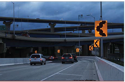
Figure 36. Photo. Example of Sequential Dynamic Curve Warning System.
Sequential Dynamic Curve Warning Systems (SDCWS) have been implemented as a countermeasure on two-lane rural highway curves as a means to reduce vehicle operating speeds and improve curve delineation. SDCWS are horizontal curve chevron signs with solar powered flashing lights embedded in the sign, as shown in Figure 36. Four States collectively installed 12 SDCWS along horizontal curves on two-lane rural highways. These sites were identified based on a high-crash history, as well as vehicle operating speeds that exceeded the posted speed limit. The study has found that both operating speeds and crash frequency have been reduced by SDCWS installations. See Appendix E for more information.
Relative Cost
The cost of these systems varies, depending upon the specific design and the availability of a power source. This countermeasure is moderate cost.
SIGN MAINTENANCE
Regardless of whether an agency has basic or enhanced signage countermeasures, road agencies should consider maintenance requirements when deciding what countermeasure to use, and carry out maintenance activities on a regular basis to ensure continued safe travel. These maintenance activities include:
- Replace or repair damaged or knocked down signs. Signs that are damaged through vandalism, accidents, or storms, as seen in Figure 37, should be repaired or replaced as soon as feasible.
- Replace faded signs and those with low levels of retroreflectivity. The various signs discussed in this report are visible at night because they are made with retroreflective sheeting material. Few, if any, are illuminated by external lighting. Even though the retroreflectivity of sheeting material has improved to provide brighter and longer lasting signs, all signs deteriorate over time. Signs lose their color and retroreflectivity and eventually they are no longer visible to motorists from a distance, as seen in Figure 38. Therefore, the MUTCD requires agencies to use an assessment or management method designed to maintain sign retroreflectivity at or above the minimum levels in Table 2A-3. For alternative methods see Maintaining Traffic Sign Retroreflectivity (FHWA-SA-07-020) Replace any signs found to be ineffective as soon as practical.
- Cut back foliage to improve the sight distance through the curve and increase visibility of traffic control devices. Agencies can improve safety at a horizontal curve by maintaining the longest possible sight distance through the curve and to the various traffic signs. During the growing season, grass, weeds, brush, and tree limbs can limit a driver's view of the road and signs, as seen in Figure 39. This is why agencies should make periodic inspections of the roadway to identify and correct these situations. For more information, see Chapter 5 of this publication.
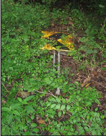
Figure 37. Photo. Example of a Chevron sign on the ground.
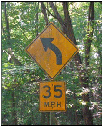
Figure 38. Photo. Low Retroreflectivity sign example.
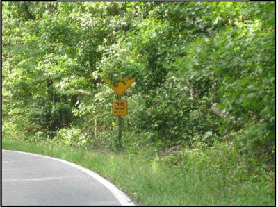
Figure 39. Photo. Curve warning sign covered by foliage.
More practical tips for controlling vegetation overgrowth are found in FHWA's Vegetation Control for Safety
