CHAPTER 3. MARKINGS
Curve delineation can be critical for a driver to navigate roadways successfully. This is of particular importance for nighttime driving, when cues to changes in alignment (such as trees and guardrail) may not be readily visible. Pavement markings located within the driver's focus provide continuous information to help drivers position their vehicles in the roadway correctly. As such, pavement markings provide a good first option for horizontal curve countermeasures on paved roadways of sufficient width. Delineators–a retroreflective device mounted on a post or roadside barrier along the side of the roadway–also provide the driver with visual cues to the roadway alignment, although they are point sources and placed slightly outside the main focus area. Placing other markings (especially to reduce speeds) on the pavement in advance of the curve can also help drivers successfully negotiate curves.
The following discussion provides information on pavement marking countermeasures, marking material options, and maintenance and cost considerations. All example markings are from the MUTCD unless otherwise noted.
LONGITUDINAL PAVEMENT MARKINGS
Center lines and edge lines are the primary types of longitudinal pavement markings on two-lane roads. They delineate the travel lane for the driver, assist in lane placement to avoid collisions with other vehicles, and provide a preview of changing roadway alignment. Unless center lines and edge lines are required for the entire roadway, the MUTCD permits their use at specific locations, such as around a curve. However, since markings typically have a shorter life-span than many other devices, particularly at curves where vehicles cross these lines more frequently, the life-cycle cost of markings should be considered before installing them only at curves.
The MUTCD Sections 3A.05 and 3A.06 provide guidance on colors, widths, and patterns for longitudinal pavement markings. This publication, which focuses on two-lane roads, will highlight yellow markings used to delineate the separation of traffic traveling in opposite directions and white markings used to delineate the right-hand edge of the roadway. Normal line widths are 4 to 6 inches and wide lines are at least twice the width of a normal line.
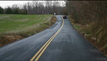
Figure 8. Photo. Center line for No Passing on horizontal curve.
Center Line
When considering pavement markings to delineate a curve, the center line is usually the first countermeasure to apply (Figure 8). A center line helps drivers keep their vehicles on the correct side of the road (MUTCD Sections 3B.01 and 3B.02).
Design
For any section of two-way, two-lane roadway, where passing is allowed in both directions, the basic center line marking is a broken, or dashed, yellow line. On some curves where the horizontal curvature, vertical curvature, or other conditions reduce the passing sight distance for one or both directions of travel below the minimum values given in Part 3 of the MUTCD, a solid yellow line is used to inform motorists of the no-passing regulation where the restriction exists for either direction of travel. For segments where passing is prohibited in both directions, a solid yellow line is used for both directions (i.e., double line pattern), separated by a gap approximately equal to the width of a normal line. To be effective at night when approximately half the crashes occur, the pavement marking must be retroreflective.
Applications
Table 1 summarizes MUTCD criteria for center line markings of two-way roads.
Table 1. MUTCD requirements for center line markings on paved two-way streets.
| Area type | Road Class | Lanes | Avg. Daily Traffic (ADT) | Travel Width (feet) |
||
|---|---|---|---|---|---|---|
| REQUIRED | Urban | Collectors | Arterials | 2 | 6,000 + | 20+ |
| All | All | 3+ | ||||
| RECOMMENDED | Urban | Collectors | Arterials | 2 | 4,000+ | 20+ |
| Rural | Collectors | Arterials | 2 | 3,000+ | 18+ | |
| MAY CONSIDER | Any | Any | 2 | Any | 16+ | |
Adding center lines at curves, even if it not required or recommended per the MUTCD, is worth considering as these center lines provide delineation of the change in alignment to the driver. For example, in some Minnesota counties, severe crashes were over-represented on curves with ADTs between 400 and 1000 vehicles per day. This would indicate there may be a benefit to striping curves in that range of volumes, even though it is lower than what is required or recommended by the MUTCD. Also, the Speed Typology Study (Council et al., 2010) indicated most speed-related crash problems on horizontal curves are on collector and local routes.
The MUTCD also states that "engineering judgment should be used in determining whether to place center line markings on travel ways less than 16 feet wide because of the potential for traffic encroaching on the pavement edges, traffic being affected by parked vehicles, and traffic encroaching into the opposing lane." Placing a center line marking only in the curve may be appropriate, but it must follow the design parameters to indicate appropriate passing requirements, as the MUTCD states that "a single solid yellow line shall not be used as a center line marking on a two-way roadway."
Therefore, the addition of this pavement marking should be the first countermeasure considered, at a minimum, when an agency identifies a curved section of roadway as a potential safety problem and the road segment does not have a center line. When the curve carries a low traffic volume (fewer than 400 vehicles per day), the pavement is less than 16 feet wide, or it is an unpaved road, consider using post delineators, chevrons, or curve warning signs in lieu of a center line.
Effectiveness
A variety of studies exist on center lines, but none of these are specific to the application of center lines placed only in horizontal curves. One study suggests that there is a connection between improved retroreflectivity of the yellow center line and reduced crashes on rural two-lane roads (Carlson et al., 2013). The CMF Clearinghouse lists two reduction factors for the installation of center lines on roadway segments (both CMFs are 3 stars), with a 1-percent decrease for injury crashes and a 1-percent increase for property damage only (PDO) crashes (Elvik and Vaa, 2004). However, significant reductions in serious and minor injury crashes can also be realized:
- 45-percent reduction when center lines, edge lines, and delineators are installed on roadway segments (CMF is 4 stars) (Elvik and Vaa, 2004).
- 14-percent reduction when center lines and edge lines are installed at sites with higher incidences of crashes (CMF is 3 stars) (Al-Masaeid, 1994).
- 24-percent reduction when center lines and edge lines are installed on rural highways (CMF is 4 stars) (Elvik and Vaa, 2004).
Relative Cost
This countermeasure is low cost.
Edge Line
The edge line pavement marking defines or delineates the edge of a roadway (MUTCD, Sections 3B.06 and 3B.07) (Figure 9). It provides a visual reference to guide motorists and helps reduce drifting onto the shoulder and roadside area. Edge lines provide the added benefit of guidance away from the glare of oncoming headlights. When used with the center line or adjacent lane line for a multilane road, it defines the travel lane for the road user.
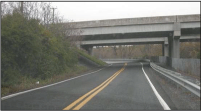
Figure 9. Photo. Edge lines.
Design
Edge line markings are a solid white line at the right edge of the travel lane for undivided roads.
Applications
The MUTCD requires edge lines not only for freeways and expressways, but also for "…rural arterials with a traveled way of 20 feet or more in width and an ADT of 6,000 vehicles per day or greater." Edge lines are recommendedfor "…rural arterials and collectors with a traveled way of 20 feet or more in width and an ADT of 3,000 vehicles per day, "and any other paved roadways where an engineering study identifies a need for edge line markings. Edge lines may be used on other roadways, with or without center lines, based on engineering judgment, but the risk of head-on crashes where center lines are not used must be considered.
The Missouri Department of Transportation (MoDOT) has found that applying an edge line to two-lane rural roads with AADT between 400 and 1,000 vehicles per day has reduced total crashes for all crash types by 15 percent. The study also found that the application has reduced severe crashes by 19 percent. See Appendix C for more information.
As with the center line, edge lines may be applied just prior to and within the curved section, as delineation of the curve is usually more critical than for tangent sections. Also, the edge line width can be increased to provide a better visual perspective of the roadway. Figure 10 and Figure 11 show the same stretch of road with a 4-inch edge line and with an 8-inch edge line, respectively. As can be seen in these photos, the curve of the road is better delineated in Figure 11.
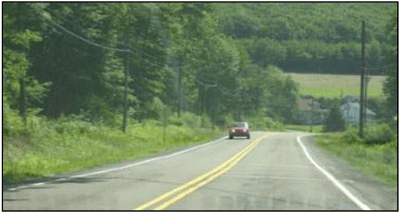
Figure 10. Photo. Roadway with 4-inch edge line.
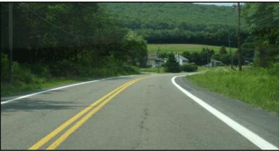
Figure 11. Photo. Roadway with 8-inch edge line.
Effectiveness
Several studies indicate that using edge lines results in crash reductions on two-lane roads. The CMF Clearinghouse lists five reduction factors from a single study for the installation of edge lines on curves, with a 26-percent or 33-percent reduction for all crash types in rural applications (CMF is 3 stars). The larger reduction was for 9-foot lanes while the smaller included lanes up to 11 feet wide. Specifically for run-off-road crashes, reductions of 11-percent were found for urban applications (CMF is 3 stars) and 13-percent for rural applications (CMF is 2 stars). Furthermore, the CMF Clearinghouse lists a 4-percent reduction for speed-related crashes in rural applications (CMF is 2 stars) (Tsyganov, 2009). A 2012 study shows that 5-inch or 6-inch line widths provide safety benefits on rural two-lane roads beyond the more typical 4-inch width (Park et al., 2012). Although the 2012 study's findings are not specific to horizontal curves, the safety benefits realized on tangent segments can also potentially also apply to curves.
Relative Cost
This countermeasure is low cost.
OTHER LONGITUDINAL DELINEATION
Delineators may also be used to communicate the roadway alignment to the driver. Delineators can be used on roads that are not paved and play a slightly different role than pavement markings since they are placed outside the edge of the traveled way.
Delineators
A delineator is a retroreflective device mounted above the roadway surface and along the side of the road in a series to indicate roadway alignment (Figure 12). Delineators are the only longitudinal guidance devices that can be used for unpaved roads. For paved or unpaved roadways, delineators are most effective at night and during adverse weather when the roadway is wet or covered in snow.
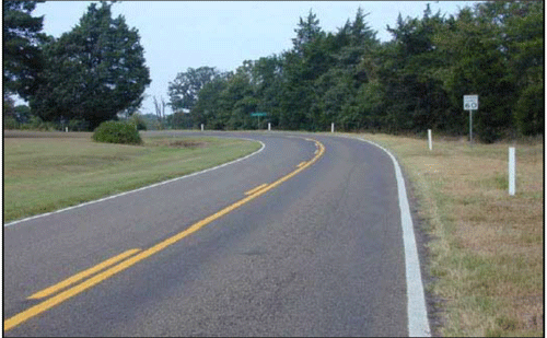
12. Photo. The color of delineators must match the color of the adjacent edge line. Source: Texas Transportation Institute.
Design
The retroreflective portion of the delineator is typically either a circular button reflector or a rectangular piece of sheeting with a minimum diameter/width of 3 inches. They are usually mounted on flexible or lightweight breakaway posts 4 feet above the pavement, except where barriers are present. For more information on delineators on barriers, see Chapter 6.
Chapter 3F of the MUTCD requires the color of the delineators to match the color of the adjacent edge line. For example, on a curve on a two-way road, the edge lines on both sides of the road are white, which means that if delineators are used on the left and/or right side of the road they must also be white.
Applications
Delineators should be placed 2 to 8 feet outside the outer edge of the shoulder, or if appropriate, in line with the roadside barrier. The delineators should be placed at a constant offset, to appropriately reflect the alignment. An exception to this occurs where an obstruction is between the pavement edge and the line of delineators. In this case, the line of delineators must be transitioned to be within the innermost edge of the obstruction. Delineators should be spaced 200 to 530 feet apart on mainline tangent sections. On approaches to and within curves, they should be spaced as recommended in Table 3F-1 of the MUTCD. The goal on curved alignments is to have several delineators simultaneously visible to the driver to show the direction and sharpness of the curve.
Effectiveness
There is no published research documenting the safety effects of installing delineators specifically on horizontal curves as of yet. One study has shown a 4-percent increase in injury crashes and a 5-percent increase in property damage crashes when delineators are installed in rural areas (both CMFs are 3 stars) (Elvik and Vaa, 2004). However, the same study showed that the combination of center lines, edge lines, and delineators led to a 45-percent reduction of injury crashes on all roadway types (CMF is 4 stars) (Elvik and Vaa, 2004).
Relative Cost
This countermeasure is low cost.
The cost of post delineators applied to a single curve will vary depending upon the number and the material used for the post and reflector. These devices also need to be maintained, but due to their location, do not typically require the significant traffic control (such as lane closures) that is often required to maintain pavement marking and raised pavement markers (RPMs).
ADVANCE MARKINGS FOR CURVES
Pavement markings in advance of horizontal curves provide highly conspicuous, supplementary warning information and the potential to increase safety. The two pavement markings options discussed in this section are especially important for reducing speeds at curve locations where signs have proved ineffective.

Figure 13. Photo. Pavement marking for advanced curve warning.
Speed Advisory Marking in Lane
Advisory speed warnings provide essential information directly related to drivers' safe negotiation of curves. The marking supplements the curve warning sign with advisory speed plaque, by providing the same information in the driver's direct line of sight, emphasizing the message to the driver.
An example speed advisory pavement marking is illustrated in Figure 13. In this example, the markings display is "CURVE-55-MPH." An arrow symbol may be substituted for the word "CURVE" and provides the driver additional information if the curve is not visible due to alignment issues such as a crest vertical curve.
Design
Refer to Section 3B.20 of the MUTCD for design and application criteria. Elongated letters as specified in the Pavement Markings section of Standard Highway Signs and Markings are required. The elongation makes the letters easier to read by approaching motorists. Pavement marking word messages are designed with the first word in the message placed closest to the approaching driver. NCHRP Report 600 contains design guidelines as to which markings are effective in reducing speeds at horizontal curves and which markings are not as effective (p. 20-4) (see Figure 14).
| Design Guidelines | ||||
|---|---|---|---|---|
| Marking Goal |
Do this: | Do not do this: | ||
|
Reduce speeds in horizontal curves |
Curve arrow and "50 mph" text |
"Curve 55 mph" text |
Transverse lines |
"Curve Ahead" text |
Figure 14. Illustration. Design Guidelines for Pavement Markings to Reduce Speeds at Horizontal Curves. Source: NCHRP Report 600.
The advance distance at which such markings are applied depends on both the approach speed and design speed of the curve. Agencies should base advance placement distances on specific approach and curve speeds, which should be the same as advance distances prescribed for warning signs, as provided in Table 2C-4 of the MUTCD shown in Table 2.
Table 2. Table 2C-4 from the MUTCD: Guidelines for Advance Placement of Warning Signs.
| Posted or 85th- Percentile Speed |
Advanced Placement Distance | ||||||||
|---|---|---|---|---|---|---|---|---|---|
| Condition A: Speed reduction and lane changing in heavy traffic |
Condition B: Deceleration to the listed advisory speed (mph) for the condition | ||||||||
| 0 | 10 | 20 | 30 | 40 | 50 | 60 | 70 | ||
| 20 mph | 225 ft | 100 ft | N/A | — | — | — | — | — | — |
| 25 mph | 325 ft | 100 ft | N/A | N/A | — | — | — | — | — |
| 30 mph | 460 ft | 100 ft | N/A | N/A | — | — | — | — | — |
| 35 mph | 565 ft | 100 ft | N/A | N/A | N/A | — | — | — | — |
| 40 mph | 670 ft | 125 ft | 100 ft | 100 ft | N/A | — | — | — | — |
| 45 mph | 775 ft | 175 ft | 125 ft | 100 ft | 100 ft | N/A | — | — | — |
| 50 mph | 885 ft | 250 ft | 200 ft | 175 ft | 125 ft | 100 ft | — | — | — |
| 55 mph | 990 ft | 325 ft | 275 ft | 225 ft | 200 ft | 125 ft | N/A | — | — |
| 60 mph | 1,100 ft | 400 ft | 350 ft | 325 ft | 275 ft | 200 ft | 100 ft | — | — |
| 65 mph | 1,200 ft | 475 ft | 450 ft | 400 ft | 350 ft | 275 ft | 200 ft | 100 ft | — |
| 70 mph | 1,250 ft | 550 ft | 525 ft | 500 ft | 450 ft | 375 ft | 275 ft | 150 ft | — |
| 75 mph | 1,350 ft | 650 ft | 625 ft | 600 ft | 550 ft | 475 ft | 375 ft | 250 ft | 100 ft |
Applications
This countermeasure does not have an established guideline; however, the MUTCD allows for use of word, symbol, or arrow markings to supplement signs as determined by engineering judgment. This application is probably more appropriate for higher speed roads where the curve advisory speed is significantly lower than the posted speed, curves where crash reports indicate speed-related issues, and corridors where speed studies indicate excessive speeding.
Effectiveness
Currently, the CMF Clearinghouse does not have a countermeasure listed for speed advisory markings in the lane. The NCHRP 600 Human Factors Guidelines for Road Systems found that the "Curve-55-MPH" text reduced speeds on a rural road by 4 mph (Chrysler and Schrock, 2005). In addition, the NCHRP 600 Human Factors Guidelines for Road Systems found that when the curve arrow and "50 mph" text were tested on an urban roadway, vehicles significantly reduced their speeds by 10-percent at the entrance to the curve. There was also an 11- to 20-percent reduction in vehicles exceeding the speed limit (Chrysler and Schrock, 2005). Another study in the NCHRP 600 tested the a curve arrow with "SLOW" text on a suburban road and found it reduced the percentage of drivers exceeding the speed limit by more than 5 mph during the daytime and late night timeframes, but not during the evening (Retting and Farmer, 1998). Overall, after testing other combinations of symbols, words, and advisory speeds, the markings that provided advisory speeds or an action performed most effectively.
Relative Cost
This countermeasure is low cost.
Speed Reduction Markings (also known as Optical Speed Bars)
Speed reduction markings are transverse stripes spaced at gradually decreasing distances (MUTCD, Section 3B.22). The rationale for using them is to increase drivers' perception of speed and cause them to reduce their speed. As spacing between bars gradually narrows, drivers sense they have increased speed and will slow down to keep the same time between each set of bars (Figure 15). Durable marking materials are preferred because of the exposure to traffic volume over time.
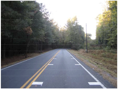
Figure 15. Photo. Optical speed bars are designed to reduce vehicle speed. Source: KLS Engineering.
Design
These white transverse stripes are only allowed where longitudinal lines are present on both sides of the lane. They must be installed perpendicular to the center, edge, or lane lines. They should be no greater than 12 inches wide, and should not extend more than 18 inches into the lane (FHWA, 2009). The spacing between the transverse markings are progressively reduced from the upstream to the downstream end of the marked portion of the lane, to produce a gradual slowing from a vehicle's initial approach speed to the advisory curve speed. The goal is to achieve the slowing before the vehicle enters the curve.
The total length of the paving-marking segment depends upon the speed difference between the higher approach speed and the lower curve speed. Table 3 suggests approximate lengths, which may be used as guidelines. The basis for the numbers is to produce a comfortable speed reduction.
Table 3. Guideline for length (feet) of speed reduction markings segment in advance of curve (Katz, 2004).
| Approach Speed, mph | |||||||
|---|---|---|---|---|---|---|---|
| 45 | 50 | 55 | 60 | 65 | 70 | ||
| Curve Speed, mph | 15 | 300 | 385 | 470 | 565 | 670 | 785 |
| 20 | 275 | 350 | 440 | 535 | 640 | 755 | |
| 25 | 235 | 315 | 405 | 500 | 600 | 720 | |
| 30 | " | 270 | 360 | 450 | 560 | 670 | |
| 35 | " | " | 300 | 400 | 500 | 620 | |
| 40 | " | " | " | 335 | 440 | 555 | |
| 45 | " | " | " | " | 370 | 480 | |
| 50 | " | " | " | " | " | 405 | |
Applications
Speed reduction markings should be reserved for unexpected horizontal or vertical curves or other feature where drivers need to decelerate in advance of the feature. The countermeasure should supplement, and not substitute for, appropriate warning signs and other traffic control devices. Agencies should avoid applying speed reduction markings to long roadway sections just to reduce traffic speed, because overuse could jeopardize the visual effect of the countermeasure. In addition, this countermeasure has been shown to be most effective in locations with unfamiliar drivers.
Effectiveness
Speed reduction markings are currently not listed in the CMF Clearinghouse, but are discussed in three relevant studies. The first study, using data from New York, Mississippi, and Texas, suggests transverse pavement markings can effectively reduce average speeds, median speeds, 85th percentile speeds, and speed variance before and after the curve both immediately after and in the long term (Katz, 2004). Speed reductions downstream of the curves varied from 0 to 5 mph. The second study, looked at speeds in advance of, within, and at the end of a 0.37-mile segment on a two-lane road with inadequate vertical and horizontal curves (Arnold and Lantz, 2007). Speeds decreased at all key locations, with statistically significant reductions of 1 to 3 mph. Speed reductions were greater in the first 90 days after installation. The third study analyzed 19 sites in Alabama, Arizona, and Massachusetts, using 2 different markings designs. The study found minor effects on vehicle operating speeds that were inconsistent (Boodlal, 2015).
Relative Cost
This countermeasure is low cost.
PAVEMENT MARKING MATERIALS, MAINTENANCE, AND COSTS
Material Considerations
Road agencies commonly use a variety of paint-based materials, or more durable materials such as thermoplastic, for center line and edge line markings. The specific material to be used may depend on an agency's equipment or willingness to contract the work. Transverse markings, such as word, symbol, and arrow markings or the speed reduction markings discussed above are typically applied with a durable marking due to the amount of wear to which they are subjected by their placement within the lane. Additional information regarding various marking materials is available in the ITE Traffic Control Devices Handbook, Chapter 9: Pavement Markings and Markers.
Other materials used by agencies to improve visibility of longitudinal lines include a variety of RPMs and "profiled" markings. These markings are particularly beneficial under wet nighttime conditions, where the retroreflectivity of the normal, flat markings is obscured. Note that the MUTCD recommends against use of RPMs either as a substitute or supplement to the edge line. The rationale is that under wet night conditions when only the RPMs are visible, edge line RPMs can confuse drivers who could misinterpret them as marking the lane line. Chapter 5 also discusses the use of rumble stripes as a supplement to center line and edge line pavement markings.
RPMs
In many situations, agencies will install RPMs to supplement or substitute for center line or lane lines. There are a variety of types, including reflective, non-reflective, and internally illuminated versions. Figure 16 and Figure 17 provide examples of RPMs. In geographic areas where snow is common, the reflective device is encased in an iron casting and recessed below the pavement surface in a grooved section to prevent damage by snow plows, as shown in Figure 17. The RPM color must conform to the color of the line for which it is used. RPMs may be used as vehicle positioning guides, to supplement or substitute for certain markings, as described in MUTCD Sections 3B.11 through 3B.14.
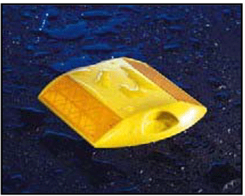
Figure 16. Photo. Retroreflective raised pavement marker (yellow for center line).
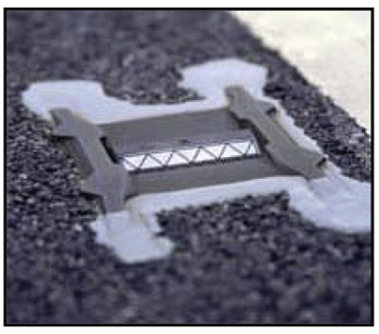
Figure 17. Photo. Snowplowable Retroreflective raised pavement marker.
Agencies typically apply the markers within a long roadway section, which is advantageous as it provides a longer visual range of delineation for motorists, especially at night (if retroreflective) and during wet conditions. RPMs also work well when applied to a single curve or a winding section of roadway. However, on curves the spacing must typically be reduced to adequately to show the alignment. The RPMs may also provide an auditory warning to the motorist who drives over them.
Effectiveness
While studies of the operational effects of RPMs have shown they can reduce the variation in lane placement and move vehicles away from the center line, studies of crash effects have produced mixed results. A study in the HSM indicates a 24-percent crash reduction on two-lane roadways with gentle curvature (less than 3.5 degrees) and relatively high volumes (greater than 15,000 vehicles per day) (CMF is 4 stars), but increased crashes for roadways with sharper curvature (greater than 3.5 degrees) regardless of the volume conditions (Bahar et al., 2004). It has been hypothesized that the increased crash frequency results from higher speeds because motorists feel safer with the RPMs providing alignment information even under wet nighttime conditions.
The same study also indicates that installing snowplowable, permanent RPMs on rural highway horizontal curves with radii less than 1,640 feet leads to an increase in total nighttime crashes of 3 percent to 43 percent, depending on traffic volumes. For rural horizontal curves with radii greater than 1,640 feet, use of snowplowable, permanent raised pavement markers leads to a 16-percent increase in total nighttime crashes for AADTs less than 5,000 vehicles per day (CMF is 5 stars), and a 1-percent to 24-percent decrease in total nighttime crashes for AADTs greater than 5,000 vehicles per day (CMFs are 3 to 4 stars) (Bahar et al., 2004).
Relative Cost
While more expensive than standard paint and thermoplastic markings, this countermeasure is low cost.
For RPMs, material costs vary significantly depending on whether the device includes the metal casing to make it snowplowable. The epoxy used to adhere the devices to the pavement must also be figured into the materials cost. However, the labor costs are often the more significant factor, particularly if the devices need to be recessed into the pavement. In considering the life cycle cost for RPMs, agencies should also factor in inspection and repair of the devices.
Profiled Pavement Markings
Agencies apply thermoplastic markings to create a profile marking, which enhances the visibility of the marking, particularly in nighttime conditions, and may also produce a slight rumble effect. Figure 18 shows an example of a profiled pavement marking.
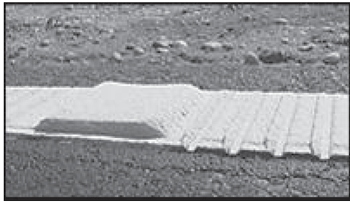
Figure 18. Photo. An example of profiled pavement markings. Source: Caltrans.
A few agencies have used this countermeasure successfully, but no research at this time provides definitive results. As such, no rating for these markings are included in the CMFClearinghouse. As snow plowing can destroy this marking, its use is typically limited to non-snow zone locations. The California Department of Transportation (Caltrans) has used two types–raised and inverted profile patterns, as shown in Figures 19a and 19b. The Oregon Department of Transportation has also used profiled markings both on top of the road surface (smooth or patterned) and recessed in the pavement surface.
Maintenance Considerations
Regardless of the marking countermeasures used, road agencies should consider maintenance needs when deciding what countermeasure(s) to use and the most cost-effective materials for the job. Maintenance activities should be carried out on a regular basis to ensure continued safe travel.
Pavement markings need to be restriped as they lose their visibility over time. Specifically, pavement markings that are made of paint-based materials have a relatively short service life–one to two years. How long an agency's pavement markings last depends on material type, installation quality, climate, and traffic volume. Markings of thermoplastic material will last approximately twice as long as paint-based materials. To maintain their effectiveness, pavement markings must be visible, especially at night and during other conditions of limited visibility. An agency's regular inspection and restriping programs are critical to ensuring pavement markings provide needed visibility for motorists.
Like pavement markings, pavement markers are subject to wear. RPMs should be inspected, and repaired or replaced regularly. The retroreflective lenses degrade or may be cracked by traffic, and adhesion of the marker may be lost. This is particularly important with snowplowable RPMs, as there have been reports of isolated incidents of loose RPMs becoming projectiles. The heavy casings of these RPMs have been reported to cause some serious injuries and few agencies have chosen to no longer use these devices.
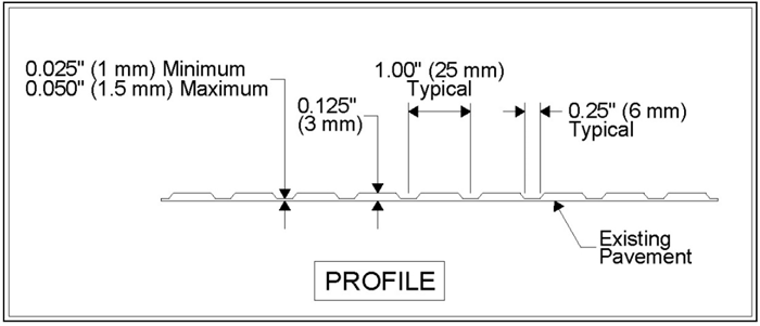
Figure 19a. Illustration. An inverted profile where depressions are made every 1 inch along the stripe.
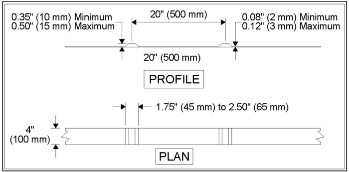
Figure 19b. Illustration. A raised profile where a thicker layer of thermoplastic is applied on 20-inch centers along the stripe.
Cost Considerations
The cost to apply pavement markings varies, depending on several factors. When applying pavement markings, an agency should consider the life-cycle cost. For example, paint has a lower initial cost than most durable materials, but paint likely needs to be reapplied every year. In comparison, a thermoplastic or epoxy material is likely to last for several years but is more expensive in initial cost. Life cycle cost needs to include or consider the cost of the materials, and the cost of the labor and traffic control needed to perform maintenance or replacement. The life of pavement markings varies greatly between agencies that need to plow their roads and those who do not.
Other cost considerations include whether the agency's own crew or a contractor performs the work and the number of horizontal curve locations that need markings. Markings placed in the lane tend to wear more quickly than longitudinal markings, and longitudinal markings on curves tend to wear more quickly than those on tangent sections. Due to these factors, and the changing cost of materials, it is not feasible to provide a cost estimate in this publication. However, the MoDOT conducted a benefit/cost evaluation of their pavement markings program, which showed an 11-percent reduction in fatal and injury crashes and an 11.2 benefit-cost ratio (Potts et al., 2011).


