
7.1 System Layout and Geometry
The lighting industry has defined standard pole spacing layout designations. These standard pole spacing layout designations are one-sided lighting, opposite lighting, staggered lighting, and median lighting.

Figure 31 – Typical Pole Spacing
Typically, one-sided spacing is used on roadways with one to three lanes, staggered spacing is typically used on roadways with three to six lanes, and opposite spacing is typically used on roadways with five or more lanes. Median lighting is typically used where the median is wide enough to accommodate poles and meet clear zone requirements, or where the poles are protected by barriers. From a capital cost perspective, median lighting may be very cost-effective as the number of poles required may be reduced by 50 percent as opposed to opposite lighting. However, median lighting may cost more to maintain.

Figure 32 – Pole Spacing
To lay out poles, the designer must undertake lighting calculations to define optimal pole spacing. Once maximum pole spacing is defined, one can lay out poles on the road drawings using a calculator and scale rule. The design should lay out poles locating a pole at a start points such as cross street, then spacing the poles evenly within the maximum pole spacing defined by the calculations, as shown in Figure 32. The pole spacing may need to be adjusted to suit driveways and utility conflicts.
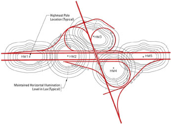
Figure 33 - Highmast Pole Spacing
For highmast lighting, the lighting calculation process is slightly different than it is for a typical roadway. It is recommended that the designer develop lighting templates for a variety of highmast pole arrangements using various fixture quantities and distributions. This can be accomplished using various combinations of individual luminaries clustered on a given pole to create the most effective overall distribution of light through trial and adjustment. By combining efficient templates, the designer is able to produce optimal light distribution for the given road geometry. The variables will include mounting height, number of luminaires, optics, and orientation of optics, wattage, light source, and photometrics.
The templates will show the pole location with luminance or illuminance levels using contour lines. The contour lines should represent different levels of illuminance or luminance. Typically, templates are developed in asymmetrical (long and narrow) or symmetrical (circular) patterns to suit road geometrics. The templates should be arranged on the site plan to show approximate pole locations, either digitally in a computer aided design (CAD) program as shown in Figure 33.
This method will give a rough pole layout and allow for optimization through trial and adjustment. Once the pole locations and pole distributions have been optimized, a lighting calculation should be undertaken for the entire interchange, defining lighting levels on the roadway. The lighting calculations will require further refinement, using trial and adjustment, until the desired levels are achieved. Highmast design will require many calculations and trial and adjustment cycles to provide an optimized design.
7.2 Scale and Inter-Relational Design
When determining pole heights, types, and luminaire wattages, the designer must consider the land use (residential, urban, downtown, commercial, industrial, etc.) and the road width. Pole height may also be limited by the reach of service vehicles used to maintain the lights. There is no exact formula for determining the optimal pole height and luminaire wattage for a given road. Factors such as pole spacing (one-sided, median, opposite, or staggered), luminaire photometrics, wattage, road geometrics, power line conflicts, lighting levels and uniformity, aesthetics, and obtrusive lighting issues are all appropriate considerations in defining optimal mounting height. In residential areas, the designer should select pole heights and fixture wattages to reduce spill light levels to those suitable for the lighting environmental zone (LEZ).
Determination of pole height and luminaire wattage is made using computer lighting design software to test different scenarios by a "trial and adjustment" process. Today's computer lighting software allows a designer to undertake calculations in minutes, thus allowing the designer to explore many more options than were practical in the past. For an interchange, highmast lighting may prove to be more effective than conventional davit-style, mast-arm or truss-style lighting. In a downtown area, post-top lighting with a mounting height of 6.0 m or less may be preferred to provide lighting structures with a more human scale, meeting the requirement for improved aesthetics. For freeway ramps, intersections or a typical city roadway, davit-style, mast-arm or truss-style lighting may prove to be the most effective.
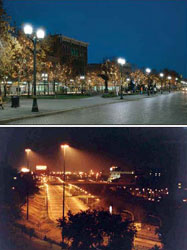
Figure 34 - Typical Lighting (Post-top and Highmast)
7.3 Adaptive Lighting
The need to reduce power consumption has stimulated significant research and product development in the field of roadway lighting. Adaptive lighting controls allow lighting levels to be reduced during off-peak periods. Simply put, a significant amount of power can be saved by varying the levels of lighting between peak and non-peak periods.
Lighting levels are established by applying criteria based on road classification(arterial, local, collector), type of pavement, pedestrian activity/conflict level. The higher the level of pedestrian conflict, the higher the level of lighting recommended. The present design practice is to use the highest pedestrian conflict/activity level for an area or segment of roadway to establish the minimum lighting levels for the portion of roadway under consideration. Once the minimum level of lighting is established, street lights have traditionally provided that level of lighting throughout the hours of darkness as adaptive technologies have been unavailable.
Pedestrian conflict levels do not necessarily remain constant throughout the hours of darkness, and in most instances the numbers of pedestrians present in a given area will be reduced in the late night and early morning hours when businesses are closed. Numbers of nighttime pedestrians may also be reduced based on the days of the week (weekday vs. weekend), seasonal factors, and other predictable dynamics. During hours of reduced pedestrian conflict, the level of lighting provided can be reduced and while meeting recommended criteria for the actual level of pedestrians present.
The amount of energy saving an adaptive lighting technology can provide depends on the variance of pedestrian conflict levels throughout the hours of darkness. During hours of reduced pedestrian conflict/activity, the level of lighting provided could be reduced (with reduced energy consumption) to the recommended criteria for the actual level of pedestrians present. An adaptive technology should not affect the distribution pattern of the luminaire, uniformity ratios are preserved, even with reductions in luminaire output. The reduction of lighting levels on local, collector and major roads can go from a high conflict to medium to low depending on predicted pedestrian activity anticipated during the course of the evening. In some cases where conflict has been designed to medium level then only a single to a low conflict/activity can be achieved. Where lighting is designed to a low pedestrian conflict then the recommended should be maintained to below those recommended.
Typically, the light output of the luminaire and lamp depreciates over their useful life, so designers must provide an initial level of lighting higher than the minimum maintained level. This compensation is achieved by applying a lighting loss factor to a lighting design. One of the components of light loss factor is lamp lumen depreciation, which defined based on lamp suppliers' published curves at the anticipated end of lamp life. This factor is typically 10 percent to 30 percent depending on the lamp type. Application of an adaptive technology may allow the street light to operate at its maintained level for the entire maintenance cycle, thus reducing power input and saving energy. One would not apply lumen depreciation to a lighting design, as the adaptive system would adjust the lamp output to maintain constant illumination on the roadway. Because lamp wattages are fixed, some areas served by street lighting are over-lighted to meet uniformity criteria, which is the driving factor in luminaire spacing. This may be the result of the lack of a lamp in the appropriate wattage (e.g., the design requires a 160-watt lamp, which is not available so a 200-watt lamp is used), or because an owner has standardized a particular pole/luminaire combination for maintenance purposes. Many roads are in fact lighted to well above recommended levels. Examples are local, collector or arterial roads where lighting levels are higher than required to meet uniformity requirement. An adaptive system could be used to rectify this issue as well as reduce levels during off peak.
Variation of lighting levels is not recommended in all lighting scenarios. Listed below are scenarios where reducing lighting levels in off-peak periods is not recommended:
- Signalized Intersections -–Signalized intersections typically include pedestrian crossings. Pedestrian conflicts with vehicles are very likely at signalized intersections even during low-pedestrian conflict periods.
- Mid-Block Crosswalks – The same rationale used for signalized intersections applies.
- Roundabouts – Due to the geometry in roundabouts and the effectiveness of fixed headlights within the roundabout circle, dimming should not be applied to these facilities.
- Rail Crossings – Rail crossing lighting is provided for detection of the trains and is not related to pedestrian conflict levels, therefore reducing lighting during off-peak periods is not recommended.
Engineering expertise is required in the application of an adaptive technology. Experienced roadway lighting designers will be able to assist owners in choosing the sites best suited for the technology. An adaptive technology is not for all roads and should be reviewed in accordance with the recommendations of IESNA RP-8 or TAC. Prior to installing an adaptive technology it is recommended a feasibility study be undertaken. The following should be included:
- Development of Design Criteria – The designer would establish design criteria for the municipality or agency for the proper application of dimming in line with standard practice.
- Inventory of Existing Facilities – An inventory of existing facilities will be required, including pole spacing, roadway classifications, pedestrian conflict levels, existing lighting levels and uniformities, configurations, etc.
- Undertake Computer Lighting Calculations – The engineer would provide calculations necessary to establish the applicability of dimming.
- Development of Cost Benefit Analysis –The engineer would assist the municipality or agency to develop and analyze the cost and benefits available.
- Development of Options and Rationale for Replacement or Retrofit of Luminaires – If existing luminaires are being retrofitted with the dimming technology, the engineer would establish criteria for evaluating where a new luminaire should be considered. Issues to be addressed would include age, condition, cost-effectiveness, etc.
- Verification and Testing – The engineer would provide independent verification of the performance of the dimming system.
- Master Planning (Recommended) to Optimize the Application of Dimming – Because communities and roadway networks are unique and operationally specific to an area, development of a dimming master plan is recommended. The master plan would define how dimming would be applied, and coordinate the retrofit of existing systems and new installations. In general, the application of dimming to new installations (new roadways or new lighting in conjunction with roadway improvements) should be prioritized to take advantage of energy savings, while retrofitting existing lighting may depend on a number of factors.
- Agreement Between Owner and Utility Companies Will Be Required – As most street lighting in North America is unmetered, an agreement between the utility company and the owner will normally be required for the owner to receive the monetary benefit associated with adaptive lighting.
An effective way to control lighting is via an adaptive lighting system. Adaptive lighting control systems can control, monitor and record the operating status of luminaires in a lighting system from a remote location using a desktop computer via the internet. Adaptive systems typically use miniature solid-state control devices that are installed in each new or existing luminaire. These systems are typically designed with software to allow an owner to build a database of the asset and monitor performance on an area-wide basis.
Additionally, luminaire locations can be identified by global positioning satellite (GPS) coordinates for easy identification, tracking and locating. With these system components in place, there is the potential to identify luminaire outages and schedule maintenance through the use of mapping software to identify and optimize maintenance routes. Using the system software, one can build up a database of the inventory and asset condition to improve scheduled maintenance.
7.4 Performance Based System Design Relating to Environmental Impacts (e.g. Outdoor Site-Lighting Performance - OSP)
Much work has been done in trying to establish a comprehensive method of determining the impact of a lighting installation for a road or site. Simply focusing on the distribution from a luminaire is insufficient, since this approach ignores the reflected light from the pavement or other direction components. The Outdoor Site-Lighting Performance method is a model developed by Brons et al (20) to try to quantify the total amount of light leaving a site and the lighting's impact on abutters and the community. Other models have also been developed, but this one is included here as an example of a more holistic approach to evaluating lighting impacts.
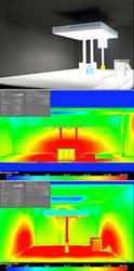
Figure 35 - Example Calculation of Lighting on Surfaces of Theoretical Box
The method essentially creates a box around a site or section of roadway and evaluates the amount of light on the sides and roof of the box as well as the maximum value of light on the vertical sides. Typical designs were investigated to get a range of values. Some provisional criteria values were then developed for discussion.
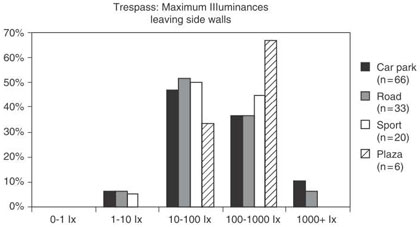
Figure 36 – Maximum Illuminance Level (Brons, 20)
| Before curfew | After curfew, glow limit (by lightin zone) | |||||||||
|---|---|---|---|---|---|---|---|---|---|---|
| Criterion slope | (%) Pass | E4 | (%) Pass | E3 | (%) Pass | E2 | (%) Pass | E1 | (%) Pass | |
| Car Park | 0.12 | 65.2 | 65.2 | 65.2 | 57.6 | 22.7 | ||||
| Roadway | 0.14 | 63.6 | 30 lx | 63.6 | 10 lx | 63.6 | 3 lx | 51.5 | 1 lx | 21.2 |
| Sport | 0.22 | 65 | 35 | 5 | 0 | 0 | ||||
Figure 37 – Proposed Glow Limits (Brons, 20)
7.5 Roadside Hazards
Clear zone is defined in the Roadside Design Guide 2011 as the total roadside border area, starting at the edge of the traveled way, available for safe use by errant vehicles. Determining the clear zone is a function of design speed, traffic volumes, the presence of fill and cut slopes, the steepness of the slopes and the horizontal curvature of the road.
Although an unobstructed roadside is highly desirable from a roadside safety viewpoint, some appurtenances such as light poles must be placed near the travel way. As roadway lighting is a road safety enhancement, poles should be placed in such a way that they do not present a hazard to errant motor vehicles. All new and replacement Luminaire support poles should be selected from those that have been successfully crash-tested. Poles should not compromise the safety of the road user. Details for reducing impact severity with the use of suitable breakaway pole base design are included in the AASHTO Roadside Design Guide (21).
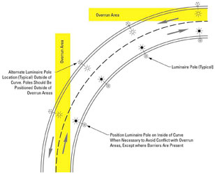
Figure 38 – Pole Spacing on Curves
Where lighting is required on roadways with small radius horizontal curvature, poles should be positioned on the inside of the curve to reduce the potential for impacts by errant vehicles that overrun the entry to the curve. If poles cannot be positioned on the inside of the curve, they should be located outside of the entry overrun areas defined in Figure 38.
Poles should be offset away from the roadway at a sufficient distance to minimize potential hazard to drivers. In urban areas with curbs and gutters, poles should be placed at the back of the sidewalks (when possible given locations of buildings and proper sidewalk width) to reduce the potential contact with motor vehicles. Breakaway base should always be used unless engineering judgment shows that pedestrian safety could be compromised. On highways and freeways, poles should be placed outside the clear zone or have a suitable breakaway device if placed within the clear zone.
A breakaway device typically attaches between the foundation and the pole to allow the pole to break away upon impact by a motor vehicle. Figure 39 illustrates breakaway base characteristics when a pole is struck by a motor vehicle. A stub height or 4 inches or less should be used to lessen the possibility for impacting vehicles to snag on the foundation of the breakaway support. Additionally the breakaway support should utilize electrica disconnects to reduce the risk of fire and electrical hazards after the structure is impacted by an errant vehicle.
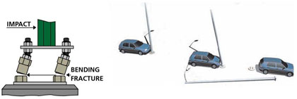
Figure 39 – Pole with Breakaway Device