RSA Projects Selected
This effort was comprised of three RSAs in different regions of the country, as shown in Table 2, which incorporated utilizing IHSDM in the standard eight-step RSA process. These sites were selected based on the following criteria:
- A demonstrated need for an RSA
- Availability of design data to input into IHSDM
- Variation in geographic location
A more detailed report of these three RSAs is included in Appendix A.
Table 2: RSAs Conducted Using IHSDM.
| Location and Host Agencies | Facility Type and Project Stage | Length of Segment Studied |
|---|---|---|
| Snake Hill Road in Glocester, Rhode Island; Rhode Island Department of Transportation (RIDOT) | Existing two-lane rural highway. | 7.4 miles |
| US Highway 2 in Kalispell, Montana; Montana Department of Transportation (MDT) | Existing two-lane rural highway. | 26.1 miles |
| US 97, Klamath County, Oregon; Oregon Department of Transportation (ODOT) | Existing two-lane rural highway and proposed roadway improvements. | 9.4 miles |
Overview of How IHSDM was used in the RSA Process
IHSDM output was reviewed by the RSA team during the start-up meeting (Step 3 in the RSA process) and during the RSA analysis workshop (Step 5 in the RSA process). During the start-up meeting one person familiar with using IHSDM described and interpreted key program results including the location of potentially critical conditions and the potential effect on crashes. These were then reviewed in detail in the field (Step 4 in the RSA process). Later, during the RSA analysis workshop, a more detailed review of the IHSDM output was conducted. The objective of this review was to more thoroughly discuss the analysis results and to compare these results with conditions observed in the field.
Data Requirements
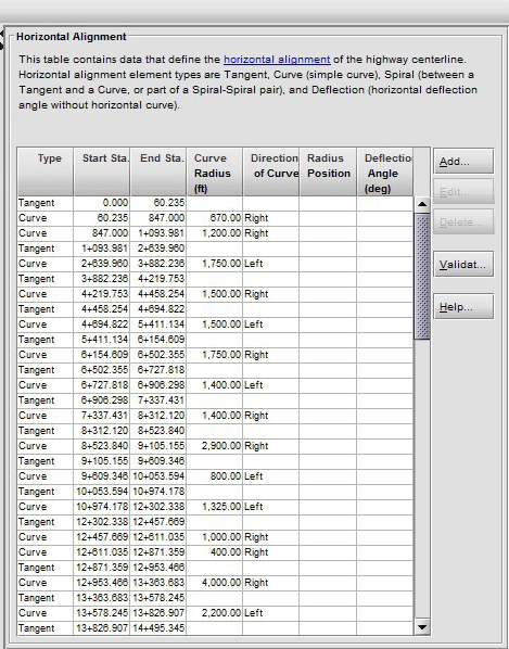
In order to analyze a roadway using IHSDM, geometric, roadside, crash, and traffic data are needed to analyze and identify conditions along the corridor. These data requirements vary for each module but the basic geometric elements required are the roadway horizontal alignment, vertical alignment, and cross-sectional data (roadway cross-section and roadside). Horizontal alignment data is represented by a series of tangent (i.e., straight) sections and horizontal curves defined by project stations. Vertical alignment data is categorized as Level I or Level II, with Level I being the complete vertical alignment data to include grades and vertical curves defined by project stationing and Level II being only vertical tangent data and no vertical curve data. However, IHSDM provides a methodology for estimating vertical curve elements with only the Level II data. The methodology is documented in the IHSDM Help Browser. Cross-sectional data includes road elements such as cross slope and superelevation and roadside elements such as obstruction offset, and roadside hazard rating. Roadway geometry data can be extracted from road design software by exporting to LandXML format and then importing into IHSDM; or may be entered manually into IHSDM via a Highway Editor graphic user interface (GUI). Roadside elements can also be translated from design software into LandXML but are usually entered manually into IHSDM via the Highway Editor due to difficulties or limitations on extraction from design software. Other data not stored in road design software such as traffic volume are also typically entered manually.

Figure 3: The IHSDM Highway Editor for entering horizontal alignment data.
In general, geometric and other data are required for both roadways and intersecting streets in order to analyze intersections using IHSDM via the IRM. Since geometric data were only available for the mainline on the corridors selected for this project the IRM was not utilized for this project. The TAM and DVM were also not used due to lack of critical data elements specific to these modules. A detailed description of the data requirements and analysis methodology for the modules used is included in Appendix B.
Assembling and Entering Data
The following summarizes the approach used in each of the three RSAs to assemble and input data into IHSDM.
Rhode Island
The RSA Team utilized the following three IHSDM modules for the Snake Hill Road corridor:
- Policy Review Module (PRM).
- Design Consistency Module (DCM).
- Crash Prediction Module (CPM).
The only geometric data available for the Snake Hill Road corridor was in the form of as-built construction plans from the 1980s. In order to use the latest geometric data and streamline all the data input process into IHSDM, the RSA team used the following process, which used a combination of aerials, GIS, as-built plans, and field visits:
- Import Google Earth aerial photo into AutoCAD (road design software).
- Create roadway centerline by tracing aerial image.
- Establish user-defined project stationing.
- Import vertical data from Rhode Island GIS (RIGIS with 5-foot interval contours).
- Fine tune vertical and horizontal alignment data from as-built plans, resulting in horizontal and vertical curve design based on user-defined project stationing.
- Import geometric data directly into IHSDM via the LandXML import tool.
- Manually enter cross sectional data from as-built plans via IHSDM Highway Editor.
- Reference crash location to user-defined project stationing.
- Manually enter crash location, crash type, and severity into IHSDM via the Highway Editor.
- Enter the remaining roadway characteristic data into IHSDM via the Highway Editor. Key elements include:
- Roadside Hazard Rating (a rating of the safety of the roadside as determined from field review/Google Earth Street View).
- Speed data (determined through review of posted speeds, which is used in the DCM, and collecting speed data along corridor).
- Average Annual Daily Traffic (AADT) volume data from RIDOT
- Obstruction offset (the distance from the centerline of the highway to sight obstructions as determined by estimating offset from Google Earth streetview and used to check stopping sight distance and passing sight distance in the PRM).

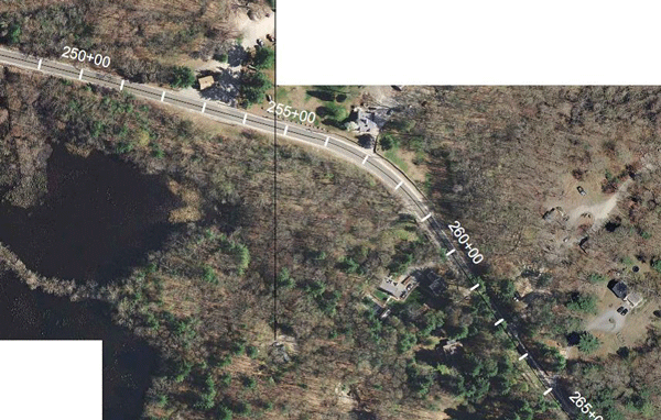
Figure 4: Snake Hill Road RSA: Google Earth aerial with project stationing.
Montana
The RSA Team utilized the following three IHSDM modules for the US Highway 2 corridor:
- Policy Review Module (PRM).
- Design Consistency Module (DCM).
- Crash Prediction Module (CPM).

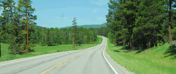
Figure 5: US Highway 2 near MP 106 in Kalispell, Montana. IHSDM was used to identify this section as having an elevated crash potential as well as a location where the speed differential between straight and curve sections of the roadway may be a concern.
As-built drawings with horizontal roadway geometry and excel spreadsheets with elevation data were provided by MDT for the section of the US Highway 2 corridor analyzed using IHSDM. The horizontal roadway geometry data was manually entered via the Highway Editor.
Since MDT provided elevation data for the roadway by milepost (MP) in an electronic spreadsheet format, the MPs were converted to project stations (accounting for station equations), then the elevation data were plotted to scale by the project team resulting in a roadway elevation profile. The team drew in the grades and connected these using vertical curves resulting in Level I vertical alignment data. The vertical alignment data was then entered into IHSDM manually via the IHSDM vertical data entry the Highway Editor. Other data was then gathered and entered into IHSDM similar to the Rhode Island Case Study.
Oregon
The RSA team utilized the following three modules for the US 97 corridor:
- Policy Review Module (PRM).
- Design Consistency Module (DCM).
- Crash Prediction Module (CPM).
The existing and proposed alignment for US 97 was provided to the RSA team in MicroStation format. Some data was able to be directly imported into IHSDM utilizing GEOPAK road design software; however, many elements were not able to be converted and much of the geometric data for the existing road was entered manually into IHSDM via the Highway Editor. More of the design elements from the proposed roadway were able to be converted directly into IHSDM data format. All roadside elements were entered manually.
