
II. IDENTIFY PROBLEMS AND PLAN APPROPRIATE ACTION
Road agencies can learn of damaged guardrail from several sources, an accident report is the most obvious. However, as many guardrail impacts are drive-away situations, maintenance (or other highway) personnel can identify damage that may not be obvious to the casual observer, but that could keep the guardrail from performing as intended. Once the agency receives notice of damage, make an on-site review of the damage. The first priority of a review is to determine whether the barrier can be removed — by eliminating the hazard it was intended to shield. This is seldom an option, but do not lose the opportunity to improve the roadside safety. If the barrier is to remain, then the review objective is to determine the extent of the damage, what repairs to make, and when to make them.
Three categories of functionality can be used to describe the extent of damage:
- Guardrail is no longer reasonably functional.
- Guardrail should function adequately under a majority of impacts.
- Damage should not affect the guardrail's ability to perform.
Each agency must make a risk assessment about the timing of repair for each different category of functionality. The assessment would include, among other factors, agency resources (within its overall mission), hazard exposure (how likely is it the guardrail will be hit again), and hazard severity. It is important that each agency develop guidance for when to make repairs.
ASSESS DAMAGE EXTENT AND REPAIR
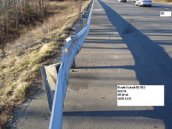
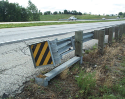
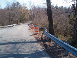 Drums, as shown, vertical panels, or cones, can be used to warn drivers of the damaged guardrail until it can be repaired.
Upon arriving at the site, clear any debris from the traffic lanes and shoulders. Place debris that cannot be hauled away at least 3 ft behind still-effective guardrail. When the damage leaves the guardrail nonfunctional, and it cannot be repaired immediately, warn traffic of the hazard by putting out temporary warning devices, such as drums, vertical panels, cones, or other devices, in accordance with the Manual on Uniform Traffic Control Devices (MUTCD), Part 6, Temporary Traffic Control, or local policy.
If a blunt end remains, take steps to minimize its danger. Crews could drop the rail forming a turndown; while not desirable, it is better than leaving a spear. In extremely dangerous situations, use a truck-mounted attenuator (TMA) or other type of attenuator. If possible, smooth any rough grading caused by the impact. Make a damage inspection report detailed enough to estimate repair parts and resources needed. Appendix A provides a sample damage inspection report (Item 1); provides information on estimating parts and materials (Item 2), equipment and tools (Item 3), time needed (Item 4), and crew size (Item 5); and a sample repair log (Item 6).
For each of the three sections of the W-beam guardrail system, the following is provided: the function of the section, examples of extent of damage, proper repair techniques, and a checklist for repairs.
STANDARD SECTION
The function of the standard W-beam section is to prevent penetration by a vehicle, either through, over, or under the W-beam and to smoothly redirect the vehicle. You can use the chart below to determine the functionality category based upon the damage to the standard section of the W-beam guardrail.
| EXTENT OF DAMAGE | FUNCTIONALITY | ||
|---|---|---|---|
|
RAIL ELEMENT SEPARATED |
1 |
||
| RAIL ELEMENT TORN | 1 | ||
| TOP OF RAIL HEIGHT ≤ 24" | 1 | ||
|
RAIL ELEMENTS INTACT FULL SPLICES TOP OF RAIL HEIGHT > 24"* |
AMOUNT OUT OF ALIGNMENT | AMOUNT OF BROKEN/BENT OR SEPARATED POSTS | 3 |
|
<6" |
0 | ||
| 1-2 | 2 | ||
| ≥3 | 1 | ||
| 6" – 12" | 0-2 | 2 | |
| ≥3 | 1 | ||
| ≥18" | NOT APPLICABLE | 1 | |
FUNCTIONALITY CATEGORIES:
1 Guardrail no longer reasonably functional
2 Guardrail should function adequately under a majority of impacts
3 Should not impair the guardrail's ability to perform
In narrative format, this chart shows: Functionality category 1 applies to any damage where the rail element is separated or torn, or the rail height is equal to or less than 24 inches. Category 1 also applies even if none of these three conditions exist, but (1) there are three or more broken, bent, or separated posts and the amount out of alignment is 12 inches or less, or (2) if the amount out of alignment is equal to or greater than 18 inches regardless of any broken, bent or separated posts. Functionality category 2 applies if the guardrail is out of alignment no more than 12 inches and no more than two broken, bent, or separated posts. Functionality category 3 applies only if the guardrail has no damage other than being out of alignment by less than 6 inches.
Damage Examples
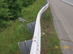
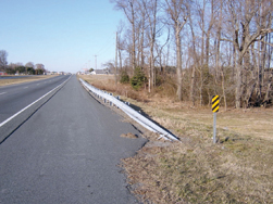
1. Damage: Guardrail no longer reasonably functional.
Rail is bent/pushed more than 18 inches out of line, and/or became less than 24 inches high, or three or more posts are broken/bent over and separated from the rail.*
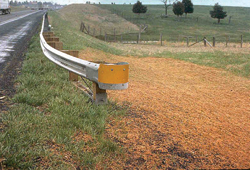
2. Damage: Guardrail should function adequately under a majority of impacts.
Rail is bent/pushed out of line less than 12 inches – rail element is intact (no tears and full splices).*
One or two posts are broken/bent over and separated from the rail – rail element is intact (no tears and full splices).*
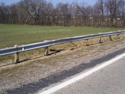
3. Damage: Should not impair the guardrail's ability to perform.
Rail is bent/pushed out of line less than 6 inches – rail element is intact (no tears and full splices; guardrail height is minimum 26-inches).*
*This is the best guidance currently available. An NCHRP study is under way to determine the level of damage that should not affect barrier functionality.
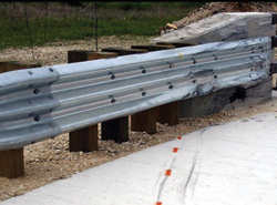
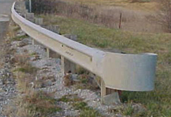
Properly Repaired Standard Section
The primary mechanism enabling guardrail to redirect a vehicle is tension developed in the rail element. Therefore, all repairs must ensure that full-tension capability is reestablished. The strong posts contribute to smooth redirection by limiting the amount of deflection and providing consistent stiffness along the rail to prevent pocketing. Repair all posts to a condition enabling them to perform their function.
A second critical element of functional W-beam is proper height. Full-scale tests show that 25-in-high W-beam (measured to the top of the rail element) will not contain a design impact (a 4,400-lb pick-up truck at 62 mi/h and a 25° impact angle).
If the length of damaged W-beam is significant, then repair the barrier to meet the current standard for height. For short sections (one or two panels) of repair, it generally is not practical to adjust the current height. When the whole run of the W-beam guardrail is substantially (3 inches or more) below the current standard (and is not repaired at this time), report the situation to management to ensure it is included in future W-beam upgrade projects.
Ensure all repaired guardrail meets your agency's current standard (except related to height, as discussed above). For repair only, use posts of a material different than the existing material only when it is impractical to obtain like-material posts. The length of W-beam to be repaired should depend on the total length of barrier and the extent of damage. If damage is severe and either the length of the whole installation is short or the amount of damage is greater than a certain percent of the total length, then bring the total system to current agency standard (including height). Values for these two criteria are arbitrary and should be set by the agency. Appendix B provides an example of one State's criteria (Note: the height criteria included in this example do not conform to the guidance in this booklet). Typical values are 100 to 200 ftto define short length and 50 percent to define portion of total length needing repair.
There is an exception to the recommendation in the previous paragraph to meet current agency standards: When existing steel post/steel block out W-beam needs repair, and it is not against agency policy, crews can use (or install) steel blocks when the posted speed is 45 mi/h or less. Back-up plates (1-ft-long pieces of W-beam rail) are required at nonsplice rail-to-post connections, and there should be no washers under any rail-to-post bolt head.
Repaired W-beam Checklist
- Tension capability is intact:
- No tears.
- Eight ⅝-in splice bolts in each rail connection.
- No rail subjected to a cutting torch is reused; any new holes are drilled.
- Height is according to standard.
- Posts are intact and firmly bedded in ground. Use a longer post (7 ft+) in front of a fill slope when there is less than 1 ftof relatively flat ground behind the post.
- No washers under rail-to-post bolt head.
- Available deflection distance in back of W-beam to a rigid vertical object (W-beam deflects as it develops tension – 3 ftis the standard distance provided; if 3 ftis not available, then add posts and/or nest rail to stiffen the system).
- Lap rail elements in the direction of traffic (upstream {approach} rail is in front of downstream {leave} rail).
- For wood block on wood posts, use toenails to restrain blocks from rotating, preferably one on each side of the block, 2 inches from the top or bottom.
- Guardrail-mounted delineators in damaged section replaced. If no guardrail-mounted delineators previously existed, install delineators per MUTCD and/or highway agency policy.
(Items 3 and 5 are most applicable for high-speed facilities and could be less restrictive for lower speed facilities.)
TRANSITION SECTION
The function of the transition section is to gradually and smoothly stiffen a semi-flexible W-beam section having a 3-ftdynamic deflection as it attaches to a rigid, non-deflecting object such as a concrete bridge parapet or (anchored) concrete barrier to prevent pocketing.
Damage Examples
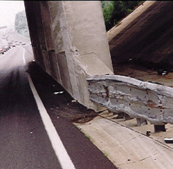
1. Damage: Transition no longer reasonably functional.
W-beam element is not attached to rigid object.
W-beam is severely pocketed in advance of the rigid object.
2. Damage: Transition should function adequately under a majority of impacts.
Rail is flattened and bent/pushed out of line less than 12 inches; rail element is intact and securely attached to the rigid object.
3. Damage: Should not impair the transition's ability to perform.
Rail is flattened / pushed out of line less than 6 inches; rail element is intact and securely attached to the rigid object.
Properly Repaired Transition Sections
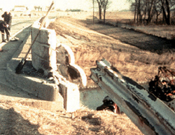
The traditional transition to concrete bridge parapets constructed before the 1990s used 3-ft, 1½-in post spacing for 25 ft in advance of the connection to the rigid object. When tested at a high speed, this design failed miserably.
Many designs meet the current testing requirements for high-speed facilities; for low speed facilities, the Texas DOT has developed a more economical[1]. All accepted transition designs incorporate four features:
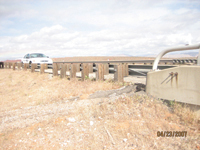 Traditional transition.
- Foremost is a strong tension connection between the W-beam and the rigid object.
- More and/or larger posts close to the rigid object.
- A nested rail element for the last 12½ ft.
- Some means to prevent wheel snagging, such as a rub rail or curbing.
The whole treatment is typically 25 ft long but could be 18½ or 31½ ft. Although metal bridge railings may not be as rigid as concrete parapets, follow the same concept of a strong tension connection, gradual stiffening, and snag prevention.
Repair transitions that did not previously contain all the above features to current standards; if that is not practical, then provide the above features on high-type facilities. (A rail-to-post bolt is not required at the locations of any extra posts when an installation is not to a standard.) On lower type facilities, it may not be practical to include all of the features to their full extent, but all repairs should have a strong tension connection. Repairs should be conducted to correct the connection even if a transition is outside the normal limits of repair within a W-beam run or if it does not contain a strong tension connection.
Repaired Transition Checklist
- Tension capability is intact:
- a. No tears in rail elements.
- Minimum of four ⅞-in-high strength bolts/threaded rods in connection to rigid object – ensure the bolt heads or nuts on the threaded rods protrude no more than ¾ inches from the face of the connection plate.
- All splices are intact (eight splice bolts in each rail connection)
- No rail subjected to a cutting torch.
- Extra/larger posts – the last post spacing in advance of the rigid object should be 1 ft, 6¾ in.
- Nested last rail element.
- Rub rail or curb to prevent wheel snagging.
- Bridge shoe lapped in the direction of the near-side traffic.
- Damaged or knocked down object (hazard) marker (if any) replaced on or adjacent to bridge parapet.
END TREATMENT SECTION
The function of the end treatment is to prevent serious injury to occupant when struck on the end and provide tension for the W-beam for side (traffic face) impacts.
Over the years end treatments have developed from simply ending the W-beam run (probably with a "shovel" end section attached – with or without the end section, providing little tension but most importantly presenting a spear) to turn down systems (that provide tension and won't spear, but that could launch a vehicle) to stand-up "safe" end treatments. The two major types of stand-up end treatments are non-energy-absorbing and energy-absorbing.
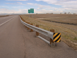
Non-energy-absorbing end treatment.
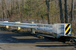
Energy-absorbing end treatment.
End treatments prevent serious injury either by being relatively soft for end-on impacts or using an energy-absorbing head slipped over the rail element to absorb the energy of the impacting vehicle by deforming the rail as it is forced into the head during shallow-angle, end-on impacts. For the stand-up end treatments, the tension function is provided by a cable attached to the rail element and anchored in the first post through a bearing plate and the post is placed in a foundation. Since the early 1990s, a strut ties post 1 together to post 2 to provide the needed resistance to the tension in the cable developed from a downstream impact.
Damage Examples
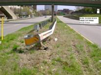
1. Damage: End treatment no longer reasonably functional.
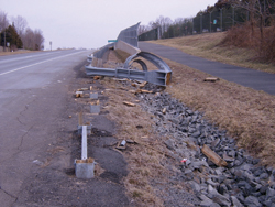
End treatment partially or fully destroyed and presents a blunt end Energy-absorbing system
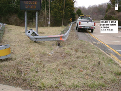
End treatment partially or fully destroyed and presents a blunt end Non-energy-absorbing system
Energy-absorbing head off of rail– probably will not ride down rail but may create a spear.
Energy-absorbing end treatments depend on the column strength of the rail element to activate the energy-absorbing characteristic of the design. The rail element must be in a straight line to develop this strength. If there are dents in the rail element, even relatively small, near the impact head, then the system will probably not perform as desired for shallow-angle, end-on impacts. Replace the dented rail element.
2. Damage: End treatment should function adequately under a majority of impacts.
Post 1 is broken such that full tension is not developed for downstream hits; however, the impact head should absorb most of a vehicle's energy for shallow–angle, end-on impacts.
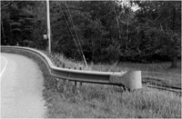
Neither the turndown nor the breakaway cable terminal (BCT) (see photos on the below) have been successfully crash tested for both a large vehicle (sedan or pick-up) and a small car. One should replace them with current standard hardware, even for minor damage. This is especially true for high-type facilities. Turndowns are easy to identify. The BCT looks similar to a MELT (Modified Eccentric Loader Terminal, see photo below), a stand-up end treatment that passed previous crash-test requirements and can be repaired when it incurs minor damage. The BCT has no strut between posts 1 and 2, standard strong posts for all posts beyond post 2, and bolts attaching the rail element to all posts.
Turndown is obvious.
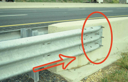
Breakaway Cable Terminal (BCT) No strut between posts 1 and 2. Standard posts beyond post 2. Bolts attach rail to each post.
Modified Eccentric Loader Terminal (MELT) Strut between posts 1 and 2. All weak posts within system. No rail-to-post bolts except at post 1.
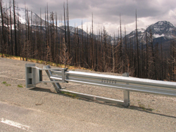
3. Damage: Should not impair the end treatment's ability to perform.
Post 1 is intact. Rail element is less than 12 inches out of line (non-energy-absorbing end treatment only).
Properly Repaired/Replaced End Treatment
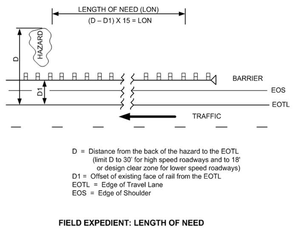
For a W-beam guardrail to adequately shield a serious hazard, the length of the W-beam guardrail must extend some distance upstream in advance of the hazard. If the W-beam guardrail is not long enough, then a vehicle can leave the roadway before it is beside the hazard and still reach the hazard the W-beam was intended to shield. This adequate distance in advance of the hazard is called the length of need (LON). Although a designer uses a special procedure to determine the LON, a simple field expedient procedure, shown in the sketch below, is to multiply the distance between the front of the W-beam and the back of the hazard (D-D1) by 15. If the back of the hazard is greater than 30 ft from the edge of the travel lane (EOTL) on a high-speed road, then 30 ft is a reasonable value for D. For lower speed roads, use a value of 18 ft (or the roadway's design clear zone[2] value, if known) instead of 30 ft.
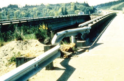
The best end treatment is probably a properly constructed buried-in-backslope (BIB) end treatment. It provides full tension for the W-beam and eliminates the possibility of injury due to hitting the end since the end is buried. When a natural backslope is near where the agency plans to completely replace a damaged end treatment, a good option is to use a BIB for the repair (conditioned that no access is required behind the W-beam at this point).
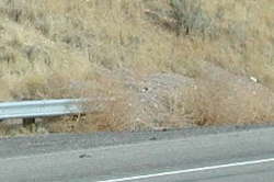
Examples of buried-in-backslope end treatments.
When repairing or replacing a stand-up end treatment with a new stand-up end treatment, you should provide the LON. However, in the majority of situations, it is either unavailable or impractical to provide the LON. Although the non-energy-absorbing end treatments perform well to minimize the hazard of the end of the W-beam, their softness allows the vehicle to pass through and behind the guardrail, and without adequate LON, could reach the hazard the W-beam was intended to shield. An energy-absorbing end treatment has an additional capability beyond developing tension and not causing serious injury on end-on impact: for shallow-angle, end-on hits, it can absorb much of the vehicle's energy and either stop the vehicle within the system itself or slow the vehicle significantly such that any downstream impact should be less severe. Therefore, use energy-absorbing systems to repair or upgrade damaged end treatments if they do not have acceptable LON and satisfactory grading, as discussed below.
Many current crashworthy end treatments are proprietary and have been designed and engineered with unique details necessary to allow them to perform properly. For example, some posts in the installations have bolts connecting the rail to the post while others do not. Also, most designs have evolved to make them more effective as well as more economically competitive. Therefore, before beginning repair on these systems, or installing new as replacements, be sure you have the manufacturer's shop drawings and installation manual for the particular model on site.
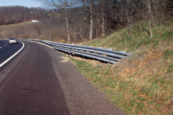
Grading: All accepted end terminals (except the BIB) were tested on flat ground. Therefore, it is best to duplicate this condition in the field so the end treatment has the best chance of performing as intended. This is generally accepted as being provided when there is 5 ft of relatively flat ground (IV:10H or flatter) behind the first post of the system (and gradually tapered back to the existing cross section in advance of the end treatment), as shown below.
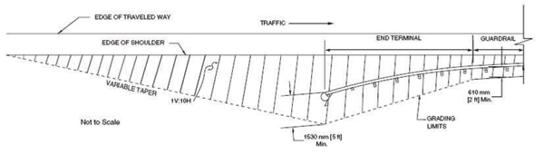
Recommended Grading Plan.
Source: Roadside Design Guide
The grading downstream of the end treatment should be available clear zone in accordance with the LON concept describe above. Also, because the posts of the system are designed to break off or bend upon end-on hits to allow the vehicle to continue down or through the system, ensure whatever posts remain after breaking or bending extend no more than 4 inches above the ground.
The previous recommendation to use energy-absorbing end treatments is re-emphasized because the 5 ft flat grading is seldom achievable in the field.
Guidelines for the Selection of W-beam Barrier Terminals developed by FHWA, provides additional information on the selection and performance of the different currently accepted end treatments. The CD-ROM (Publication Number FHWA-SA-06-19) containing these guidelines can be obtained from the FHWA Report Center. Fax requests to (301) 577-1421 or email requests to report.center@fhwa.dot.gov.
The Vermont End Terminal is a relatively inexpensive end treatment that provides both tension and a "safe" impact for lower speed (≤ 45 mph) facilities: (Additional information on this end treatment is available in the AASHTO Roadside Design Guide (RDG), chapter 8). Its use is also appropriate on a higher speed facility at the approach to a STOP sign. It uses a typical cable to develop the required tension and a radius W-beam element to prevent spearing. It is also fairly easy to construct.
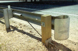
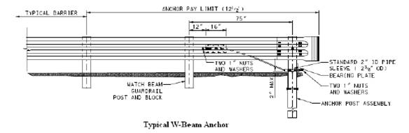
When an end treatment's only function is to develop tension, such as when used at the downstream end of a run of barrier (that is outside the clear zone of opposing traffic), an economical system is to simply attach the typical cable to the last rail element and anchor the cable in the last post that uses a steel foundation tube for resistance (see photo and figure on following page).
Repaired/Replaced End Treatment Checklist:
- Use no interchanged parts from different manufacture's systems for parts unique to the particular end treatment being repaired.
- For energy-absorbing systems, place the head completely onto the rail element.
- For energy-absorbing systems, the cable anchorage to the rail element allows the cable to release from the rail if the head slides.
- Post 1's top part will separate from its foundation for end-on impacts.
- Replace any damaged posts within the end treatment that were originally breakaway or yielding posts with breakaway or yielding posts approved by the system's manufacturer.
- Grading provides no more than 4 inches above ground to the strut or to what will remain as a stub.
- Bearing plate is properly oriented.
- Cable is tightened to a taut condition; cannot lift up on the cable more than 1 inch.
- Retroreflective object (hazard) marker in place on non-buried end treatments per highway agency policy.