RSA No. 1-Defense Highway/Burma Road Corridor, Middletown, Rhode Island
| Project Overview | |
| Project Location | Coddington Highway (in the vicinity of Gate 10) and Gate 17 Access Road from Gate 23 to Gate 32 |
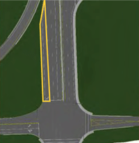
| Planned Improvements |
|
| Project Environment | Suburban |
| Project Design Stage | Preliminary Concept (0 to 1%) |
| Project Owner(s) | Rhode Island Department of Transportation, Aquidneck Island Planning Commission, US Navy |
| RSA Overview | |
| Date of RSA | August 2 - 4, 2010 |
| RSA Stage(s) | Pre-construction (planning) and operational stage and RSA of existing roads |
| RSA Team | Representatives from the Federal Highway Administration , Middletown Police Department, Naval Station Newport, Rhode Island Department of Transportation, and Vanasse Hangen Brustlin, Inc. |
| 3-D Visualization Overview | |
| Level of Effort | 100 hours were expended to model the connector road alignment, and an additional 40 hours were spent modeling the two pairs of intersection alternatives. |
| Information Provided by Designers |
|
Project Background
The objective of this study-which was cosponsored by the Rhode Island Department of Transportation (RIDOT) and the Aquidneck Island Planning Commission through the Aquidneck Island Technical Steering Committee and funded by the Federal Highway Administration (FHWA) Office of Safety-was to complete an RSA for a possible future bypass corridor in Middletown, Rhode Island on Aquidneck Island. The subject corridor included a preliminary concept 2/3-mile-long roadway alignment across the US Navy's Naval Station Newport (NAVSTA), the third largest employer in the state, which would provide a critical north-south link between Coddington Highway and Gate 17 Access Road.
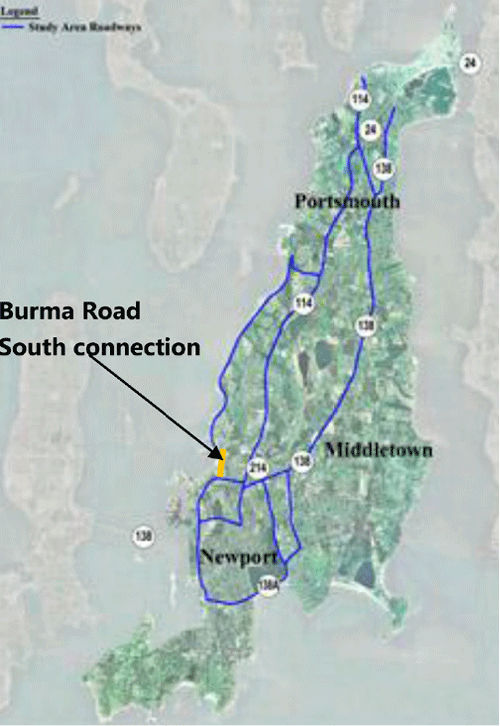
Figure 4: Graphic showing primary routes in Aquidneck Island Transportation Study
Currently there are two primary north-south routes on Aquidneck Island that connect Newport in the south with Portsmouth to the north: W. Main Road (SR 114) and E. Main Road (SR 138) (see Figure 4). In general, both facilities have a four-lane cross section with two lanes in each direction. The large number of intersecting streets, driveway access points, and traffic signals, coupled with few exclusive turn lanes, creates significant delay for traffic seeking to go from one end of the island to the other. In response to this congestion, a preliminary concept alignment of a new limited-access roadway across the NAVSTA facility was proposed. (Note that "limited-access" refers to the use by the general public, as the access and operations with respect to the US Navy and its facilities must not be adversely affected in any way.) The proposed roadway-referred to as Burma Road South-would parallel W. Main Road and connect intersecting roads Coddington Highway and Gate 17 Access Road. The corridor would continue north on Burma Road until it ends at Stringham Road in the north. As part of the Aquidneck Island Transportation Study, it was noted that a new alignment will be considered to extend Burma Road to the northeast and ultimately connect to Route 24.
Because the construction of the new Burma Road South would likely provide an appealing alternative route to W. Main Road and E. Main Road, an additional and entirely different set of users may begin to utilize the adjacent roadways (including Coddington Highway and Burma Road) as a bypass corridor to avoid the congestion of W. Main Road. Consequently, these roadways were analyzed during the RSA, not only in consideration of their existing conditions but also how the new "bypass" use may present an additional set of safety concerns.
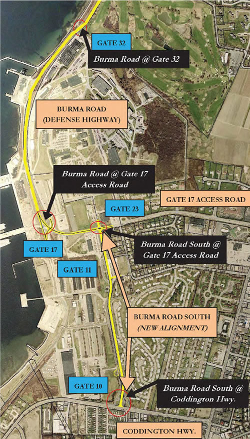
Figure 5: Limits of the entire study area for the RIRSA, including NAVSTA gates 10, 11,17, 23, and 32
The RSA included a field analysis of Coddington Highway at Gate 10, Gate 17 Access Road at Gate 11, Gate 17 Access Road at Burma Road, and Burma Road at Gate 32, as well as a thorough review of the 3-D model of the preliminary concept Burma Road South alignment. Figure 5 shows the full extent of the RSA study area, and Figure 6 depicts the limits of the area incorporated in the model.
Not only did the 3-D visualization bring to life a roadway that was in the preliminary concept design stage, it also enabled the RSA team to traverse (in a virtual sense) portions of the secured NAVSTA facility to which it did not otherwise have access. While the confines captured by the model were limited to the planned Burma Road South and its northern and southern termini, the total RSA study area exceeded the modeled area significantly along the north-south corridor.
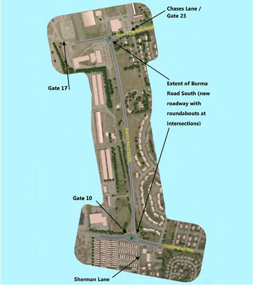
Figure 6: Plan view of area modeled as part of the RI RSA (roundabout alternative)
The RSA included a field analysis of Coddington Highway in the vicinity of Gate 10 and Gate 17 Access Road, as well as a thorough review of the 3-D model of the preliminary concept connector road alignment. Two alternatives were reviewed as part of the preliminary concept design of Burma Road South: the first included signalization of the intersections at the north and south limits, while the second included roundabouts. Figure 7 shows an image of Coddington Highway at the proposed connector road as viewed from each 3-D model.
Information used by the RSA team to conduct the review included the following:
- Crash data (2007-2009)
- Existing (2009) Average Daily Traffic (ADT)
- Projected (2030) ADT
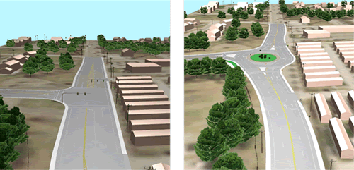
Figure 7: Images from both 3-D models comparing the signalized intersection and roundabout alternatives at Coddington Highway and the proposed connector road (Burma Road South)
Key RSA Findings and Suggestions
Three-dimensional visualization was instrumental in the RSA team's identification of a variety of potential safety issues-and not just those exclusive to the proposed designs.
Table 3 presents some key safety concerns and suggested actions along existing roadways that were either detected or reinforced by review of the 3-D visualization.
Table 3: Selected safety issues and suggested mitigating actions on modeled section of roadway
| Selected Safety Issue | Suggested Action |
|---|---|
|
Excessive speeds Overall pavement width of Coddington Highway is 55-60 ft, including outside travel lanes that measured 15-18 ft wide. Wide travel lanes encourage speeds in excess of the posted speed limit of 25 MPH. |
Near-term Restripe Coddington Hwy to provide three-lane cross section (a through lane in each direction and two-way left-turn lane [TWLTL]) with bike lanes. If roadway is restriped, consider conducting speed study to evaluate appropriateness of posted speed limit. |
|
Sight distance limitations and visual detractors
Driver sight distance is hindered at the intersection of the connector and Gate 17 Access Road by combination of factors, including trees, poles, and sun-glare at dawn and dusk. |
Near-term Restripe existing pavement on Coddington Hwy to provide three-lane cross section(through lane in each direction and TWLTL) with bike lanes. The TWLTL would remove left-turning traffic from inside through lanes. Install backplates on the traffic signal heads for Gate 17 Access Road. Intermediate-term Consider removal/relocation of sight distance obstructions from the intersection of Gate 17 Access Rd/Gate 11. Long-term Consider rebuilding Coddington Hwy to flatten vertical curve. Consider installation of roundabout at Coddington Hwy/Sherman Ln/Burma Rd South to eliminate traditional left turns at intersection and slow approaching traffic through deflection-based design. Consider installing raised median along Coddington Hwy west of Burma Rd South to eliminate left turns. Consider installation of roundabout at intersection of Gate 17 Access Rd/ Gate 11; being a feature of the roadway itself, roundabout would lower the driver's line of sight compared to a traffic signal, thereby lessening the impact of the sun's glare. |
|
Access management concerns Close proximity of access points long Coddington Hwy. |
Near-term Restripe Coddington Hwy to three-lane cross section with bike lanes. Long-term Consider roundabout installation at Coddington Hwy/Sherman Ln/Burma Rd South. Consider installation of raised splitter islands on Coddington Hwy to control left turns. |
|
Peak-hour turning movements Because of the proximity between Chases Ln/Gate 23 and Burma Rd South along Gate 17 Access Rd, the heavy peak-hour turning volumes |
Near-term Extend the eastbound Gate 17 Access Rd left-turn lane at Chases Ln to provide additional storage for turning vehicles. Long-term If the existing traffic signal is removed and a roundabout is constructed at the |
Table 4 presents several suggestions pertaining directly to the preliminary concept designs that were made as a result of the review of the 3-D model. The final suggestion pertains to nonmotorized users along the Burma Road South corridor, and Figure 8 illustrates the sidewalk accommodations provided in the preliminary concept design.
Table 4 : Suggestions on preliminary concept designs for proposed Burma Road South
| Suggestion |
|---|
| Shift proposed Coddington Hwy roundabout to the east so that Sherman Ln can become fourth leg; this should also improve sight distance at the vertical crest curve by moving the roundabout further up the hill. |
| Incorporate lighting in roundabout design to improve nighttime visibility and awareness of conditions. |
| Emphasize deflection in approach leg geometry to enhance speed reduction for oncoming vehicles. |
| Because there may be future short-term need for NAVSTA to utilize Gate 10, design should accommodate a suitable connection. |
| Characteristics of pedestrian and bicycle traffic should be considered in the design of Burma Rd South. As a limited access facility, vehicle speeds will likely be high and expectancy of pedestrians may be low. Therefore, a parallel shared use path may be preferable to accommodate pedestrians. Bicyclists may also be accommodated on this facility, especially less-experienced bicyclists. Commuter bicyclists, already present on Burma Road to the north, could use a paved shoulder, which would also provide a safety benefit to motorists. A shared use path to the east of the proposed roadway will also provide connectivity to the neighboring residences. (Likewise, a pedestrian facility on the west side - either a sidewalk or a shared use path - would not be able to access NAVSTA and is therefore less critical.) In addition, Coddington Hwy and Burma Rd both currently have (or will likely have in the future) designated bike lanes, therefore a bikeable shoulder would provide consistency with the rest of the corridor. Further discussion with the stakeholders regarding the accommodation of pedestrians and bicyclists is warranted. |
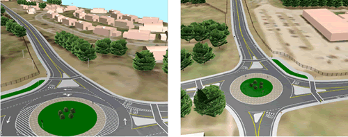
Figure 8: Proposed crosswalk and sidewalk accommodations along Burma Rd South, looking north from Coddington Hwy (left) and south from Gate 17 Access Rd (right)
Selected Issues beyond the 3-D Model
While the use of 3-D visualization constituted a major part of the study, the Defense Highway/Burma Road Corridor RSA also included a traditional field review of existing conditions in portions of the study area that did not include design visualization. In addition to the areas already mentioned, the RSA analysis also focused on the intersections of Gate 17 Access Road/Gate 11 and Burma Road/Gate 32. Table 5 presents a few such safety issues and suggested actions.
Table 5 : Selected safety issues and suggested actions for areas beyond the 3-D model
| Selected Safety Issue | Suggested Action |
|---|---|
|
Horizontal curvature There is a very sharp horizontal curve for the through movement at the intersection of east-west Gate 17 Access Road and the north-south Burma Road, with no advance warning of the curve for approaching drivers. Near Gate 32, Burma Road crosses the railroad tracks at-grade via a pair of reverse horizontal curves. Because of their low design speed, the curves are posted at 25 MPH, which violates driver expectancy since the remainder of the Burma Road corridor is posted at 35 MPH. |
Near-term Install advance curve warning signs for each approach of the through movement along Gate 17 Access Rd near Gate 11. Long-term Consider realigning the through movement of Gate 17 Access Rd near Gate 11 to provide a larger radius and higher design speed at the intersection. Burma Road/Gate 32: Consider "swapping" locations of the rail line and Burma Rd between Gate 17 and Gate 32 such that the rail line would lie to the west of the roadway for the entire corridor. This would eliminate the reverse curvature and the at-grade crossings of Burma Rd. Note that this will require extensive coordination with NAVSTA, as such action could significantly impact Gate 17 and Building 119 and present new security risks to the secured naval facilities. Consider the redesign of the reverse curvature along Burma Rd near Gate 32 to flatten the curves and increase the design speed such that the posted speed limit of 35 MPH may remain uninterrupted throughout the corridor. |
|
Multiple at-grade rail crossings Several aspects of the existing rail line location were observed to present safety issues, such as being located at the bottom of a downgrade and being adjacent to a busy intersection near Gate 11, and introducing two at-grade crossings along Burma Road within less than a mile (at Gate 11 and Gate 32). |
Long-term Consider "swapping" locations of the rail line and Burma Rd between Gate 17 and Gate 32 such that the rail line would lie to the west of the roadway for the entire corridor and the two at-grade crossings of Burma Rd would be eliminated. Note that this will require extensive coordination with NAVSTA, as such action could significantly impact Gate 17 and Building 119 and present new security risks to the secured naval facilities. Evaluate the long-term usefulness of the rail line in the overall Aquidneck Island Master Plan and consider removing it entirely if appropriate. On the other hand, if the railroad tracks can play a role in the enhancement of the area's transportation network, then consider upgrading and improving the rail infrastructure throughout the corridor. |
|
Inadequate signing and delineation The RSA team noted that the 25 MPH speed limit sign was missing along southbound Burma Rd just north of Gate 32, and there were no delineators found on the existing guardrail near the Gate 32 intersection. |
Near-term Replace the missing 25 MPH speed limit sign (the post was present but the sign was not) and install delineators along the existing guardrail near the intersection, which will improve nighttime conspicuity. |
Benefits of the 3-D Visualization
The 3-D model helped the RSA team to visualize and understand key engineering concepts, in this case the potential safety issues associated with different elements of the preliminary concept design and differences between the signalized intersection and roundabout alternatives. One of the potential benefits of a modern roundabout is a traffic calming effect on vehicular speeds at the intersection. While the departure legs are designed to allow vehicles to exit the circle efficiently, an element of horizontal deflection is incorporated into the design of the approach legs such that drivers are obliged to reduce their speeds in order to navigate the geometry. Excessive speed was a major concern on Coddington Highway, which is a four-lane arterial with a 2009 ADT of 18,600 vehicles per day. Posted at 25 mph, this roadway was characterized by exceptionally wide travel lanes (i.e., 15-18 ft) and commonly-observed speeds greater than 40 mph. During the team's comparison between a roundabout and traffic signal along this corridor, the 3-D model was invaluable in illustrating how the geometric deflection applied to each approach of the roundabout would in essence slow every vehicle that traversed this intersection. The team virtually "drove" along each approach and observed directly how the horizontal deflection would combine to command deceleration and a heightened awareness of the impending intersection (Figure 9). The visualization of the roundabouts led to a better understanding of their benefits and, ultimately, to their selection as a preferred alternative over the signalized intersection.
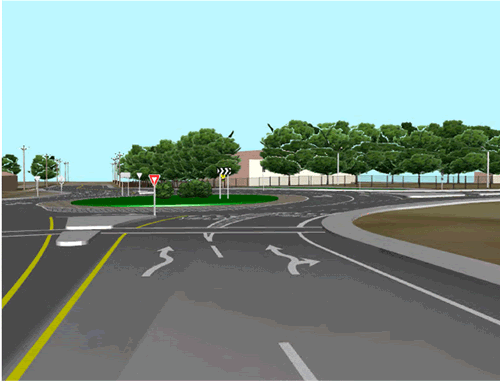
Figure 9: Driver's-eye view approaching roundabout along Coddington Highway
By being able to rotate the model and look at the design aspects from different viewpoints, the RSA team was able to suggest alignments that were more conducive to safety. For example, the model showed the Coddington Highway roundabout located just west of the intersection with Sherman Lane. The team recognized that Sherman Lane could be incorporated as a fourth leg to the roundabout by shifting the circle approximately 100 ft to the east (Figure 10). Such a design revision would eliminate a separate full-access intersection located so close to the roundabout and would accommodate all vehicle movements within the circle.
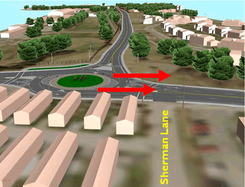
Figure 10: Image from model showing proximity of Sherman Lane to proposed roundabout
The RSA team was able to see other benefits of the roundabout design as it related to existing issues on the roadway. During the morning and evening site visits, the RSA team noted that sun glare was an issue on several roads in the study area, see Figure 11. Being a feature of the roadway itself, a roundabout would lower the driver's line of sight compared to a traffic signal, thereby lessening the impact of the sun's glare.
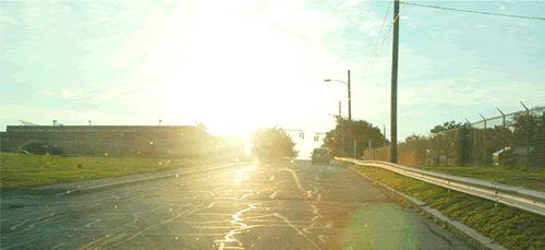
Figure 11: Early morning sun-glare as seen from eastbound Gate 17 Access Rd
The ability to describe the roundabout concept led to a broader discussion among the RSA team members regarding the implementation of roundabouts in pairs with a median installed between them. This scheme enables the conversion of all side streets and driveway access points between the roundabouts to right-in/right-out configurations by prohibiting left turns. Figure 12 presents a simple example of this approach-called the "dog-bone" concept because of its geometric characteristics. In the illustration, a single access point lies on the segment between the two roundabouts. A raised median separates the opposing through lanes on the mainline, which serves to prohibit all left turns between the roundabouts. The blue arrow illustrates the path for a vehicle seeking to turn left from the driveway, while the orange arrow shows the path of a vehicle wishing to turn left into the driveway. The same concept would apply regardless of the number of access points and side streets located within the segment, with all U-turn maneuvers being safely accommodated by the roundabouts.

Figure 12: Schematic diagram of the "dog-bone" concept
The RSA team recognized the long-term potential of Coddington Highway's conversion to a roundabout corridor with raised median, but near-term recommendations involving restriping were applied to provide an immediate impact on roadway safety (see Figure 13 and Figure 14). Additionally, as a result of the benefits demonstrated by the roundabout 3-D visualization, the City of Newport and RIDOT are currently designing a roundabout corridor as part of a bridge improvement project and the Town of Middletown and RIDOT considering the future application of multiple roundabouts. A series of roundabouts will be installed along JT Connell Highway and Admiral Kalbfus Road, and construction is expected to begin by 2020.

Figure 13: Recently implemented road diet on Coddington Hwy, Newport per RSA team recommendations (photo, left: August 2010; photo, right: January 2013)
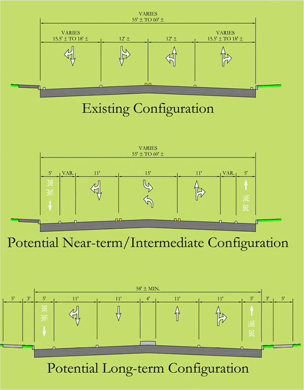
Figure 14: Existing and proposed cross sections for Coddington Hwy developed by the RSA team
RSA No. 2-Road Safety Audit of I-90 Interchanges, Belgrade, Montana
| Project Overview | |
| Project Location | Belgrade, Gallatin County, Montana |
| Planned Improvements |
|
| Project Environment | Suburban |
| Project Design Stage | Conceptual (1 to 25%) |
| Project Owner(s) | Federal Highway Administration (FHWA) and Montana Department of Transportation (MDT) |
| RSA Overview | |
| Date of RSA | August 31-September 2, 2010 |
| RSA Stage(s) | Design stage and RSA of existing roads |
| RSA Team | Representatives from the Federal Highway Administration (FHWA), Montana Department of Transportation (MDT), Montana Highway Patrol, and Vanasse Hangen Brustlin, Inc. (VHB) |
| 3-D Visualization Overview | |
| Level of Effort | Approx. 120 hours were expended to model the overall roadway study area. The proposed on-ramp designs took approximately 80 additional hours, as the 3-D model was created from a conceptual drawing. |
| Information Provided by Designers |
|
Project Background
The objective of this study was to complete an RSA of several design alternatives for a new on-ramp from Amsterdam Road (U-602) to eastbound Interstate 90 (I-90) and a proposed right-turn lane from southbound Jackrabbit Lane (N-85) to westbound Amsterdam Road in Belgrade, MT. As part of the process, this case study was designed to evaluate two adjacent interchanges: one using the 3-D modeling process, while the other was not modeled. A map showing the general study areas is shown in Figure 15. (The Amsterdam Road/Jackrabbit Lane location is highlighted in red.)
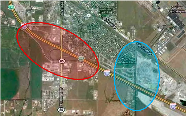
Figure 15: General project study area
The construction of an eastbound on-ramp from Amsterdam Road to I-90 was proposed as a result of a traffic study conducted in February 2009. The construction of an exclusive right-turn lane on southbound Jackrabbit Lane was also proposed. The improvements are intended to relieve congestion on Amsterdam Road during the AM peak and on Jackrabbit Lane during the PM peak. The overall purpose of the RSA was to determine if the additional on-ramp to the Interstate would potentially degrade safety when constructed within close proximity to two existing on-ramps from Jackrabbit Lane.

Figure 16: Significant traffic congestion on eastbound Amsterdam Road during weekday morning peak
The initial proposed Amsterdam Road on-ramp alternative and the proposed Jackrabbit Lane right-turn lane are shown in plan view from the 3-D model in Figure 17.
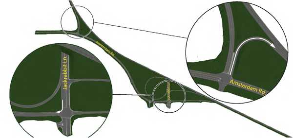
Figure 17: 3-D model plan view of RSA study area with closeups of proposed right-turn at Jackrabbit Lane and proposed on-ramp from Amsterdam Road
Information used by the RSA team to conduct the review included the following:
- Crash data (2004-2008)
- Annual Average Daily Traffic (AADT) for 2009, 2011, and 2031
- AM and PM peak hour intersection turning movement counts and projected AM and PM peak hour ramp volumes for the proposed construction
Key RSA Findings and Suggestions
The RSA team evaluated the entire study area within the project limits to identify potential general safety issues. The general findings and suggested actions discussed during the RSA are summarized in Table 6.

Figure 18: Southbound right turn at the intersection of Jackrabbit Lane /Amsterdam Road - Existing (L) and Modeled (R) Views Significant right-turn traffic volume obstructs view of approaching through vehicles
The RSA team also evaluated several design options for the proposed construction of a new on-ramp from Amsterdam Road to eastbound I-90. The 3-D model was used to visualize existing and proposed conditions, which assisted the RSAteam in performing the evaluation. The 3-D model allowed the team to evaluate the potential safety impacts of the initial design, as well as develop other alternatives during the course of the RSA. All alternatives were evaluated during the RSA workshop, including a comparison of the pros and cons associated with each. Table 6 summarizes the primary design alternatives, including advantages and disadvantages, discussed by the RSA team. Several additional variations of these alternatives were also evaluated, but are not summarized in this table.
Table 6: Comparison of the various design alternatives considered by the RSA team
| Option | Advantages | Disadvantages |
|---|---|---|
|
1: Restripe Amsterdam Road
|
|
|
|
2: Construct New EB On-ramp (3
|
|
|
|
3: Construct New EB On-ramp
|
|
|
|
4: Provide Two Through Lanes
|
|
|
|
5: Provide EB Dual Left-turn Lanes
|
|
|
|
6: Provide SB Right-turn Lane from
|
|
|
As an example of how the 3-D model was used by the RSA team, the initial design alternative (Option 2A) is illustrated in Figure 19. This alternative introduces a third eastbound access point to I-90 within the project limits (highlighted in blue in Figure 19) and signalizes the Amsterdam Road / I-90E off-ramp intersection. The RSA team discussed the possibility of altering the initial design by combining the left-turn and right-turn lanes on the off-ramp into a single shared lane (see area shaded in red in Figure 19). This alteration would provide additional space for the construction of the on-ramp, allowing for a larger design radius and speed as well as for a greater clear zone distance from existing utility poles located to the inside of the curve.

Figure 19: Modeled view of the existing (L) and proposed (R) design at Amsterdam Road and the I-90E on/off-ramp
Benefits of the 3-D Visualization
Use of the 3-D visualization allowed the RSA team to evaluate the safety effects of the initial design plan. The 3-D model assisted all team members with understanding the intended design. The majority of the team had only seen the design in 2-D on plan drawings prior to the RSA. By using the model, the team was able to visualize the "final product" as it may appear within the existing physical conditions of the study area. The 3-D model was also a major asset to team members who were not familiar with the overall RSA process (e.g., law enforcement) or roadway design plans (in 2-D format). Not only did the model introduce these members to the project, but also assisted with instructing the members as to the existing elements the team members would be looking for during the field review. This instruction and understanding increased participation in identifying problematic areas/situations (both existing and proposed) and potential opportunities for improvement.
As seen in the Key RSA Findings and Suggestions, the use of a single 3-D model for an initial design spurred the evaluation of several design alternatives. Using the model, the team was able to compare pros and cons of the various design alternatives brainstormed during the RSA workshop for the interchange with Amsterdam Road / Jackrabbit Lane. The ability to develop alternative scenarios gave the MDT other options to consider for future evaluation, which might not have been available if the RSA had not been conducted and/or the 3-D model had not been utilized. Comparing the pros and cons on the basis of safety and capacity brought an alternative to the top of the list that had not been previously considered. The interest exhibited by the MDT in this process resulted in their personnel inquiring about future possibilities for in-house design visualization to use in the design process.
The effectiveness of 3-D visualization in the RSA process was further demonstrated with the team's review of a proposed design for the new diamond interchange on I-90 at Gallatin Field Road to the east. This interchange was not modeled using the 3-D visualization tools, so that the team could compare the effectiveness of using different RSA approaches at two proximate sites. The design involved new horizontal and vertical alignments throughout the project limits, which would significantly alter roadway elevations and the surrounding landscape. Furthermore, the project would require the acquisition of right-of-way, including possible residential relocations. A conceptual illustration of the interchange is shown in Figure 20. Basic suggestions of potential safety concerns were provided; however, without a visualization of the proposed design afforded by the 3-D model, the RSA team was unable to identify detailed concerns and suggestions for improvement. The team agreed that creating a 3-D model for the RSA would have greatly helped in the assessment of the safety effects of the proposed design, particularly in terms of the over/under alignment with the railroad tracks, the roundabout configurations, the access to existing surrounding development, and the connectivity to future construction on adjacent parcels.
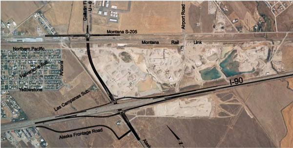
Figure 20: Conceptual illustration of the East Belgrade interchange
RSA No. 3-Road Safety Audit of Purcell Road (Route 643), Prince William County, Virginia
| Project Overview | |
| Project Location | Prince William County, Virginia |
| Planned Improvements |
|
| Project Environment | Suburban |
| Project Design Stage | 90% Design |
| Project Owner(s) | Prince William County Department of Transportation and Virginia Department of Transportation (VDOT) |
| RSA Overview | |
| Date of RSA | February 4, 2011 |
| RSA Stage(s) | Design stage and RSA of existing roads |
| RSA Team | Representatives from the Federal Highway Administration (FHWA), Virginia Department of Transportation (VDOT), Prince William County Department of Transportation, Prince William County Police Department, Fairfax County Police Department, Rinker Design Associates, and Vanasse Hangen Brustlin, Inc. (VHB) |
| 3-D Visualization Overview | |
| Level of Effort | Approximately 120 hours were expended to model the proposed designs. |
| Information Provided by Designers |
|
Project Background
The objective of this study was to complete an RSA of the proposed realignment and widening plans for Purcell Road (Route 643) in Prince William County, Virginia. The RSA also considered safety issues associated with severe horizontal and vertical alignments at the eastern edge of the proposed project limits. A map showing the general study area is shown in Figure 21.
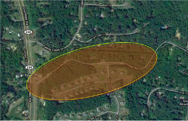
Figure 21: General project study area
The realignment and widening of Purcell Road is a project identified within Prince William County's comprehensive transportation plan. Ultimately, the vision for this section of Purcell Road is to be a four-lane divided roadway. The first stage of the project is to realign and widen Purcell Road from Dumfries Road to approximately Vista Brooke Drive (Route 3305). The intent of the realignment and widening is twofold: first, the initial phase of the project will establish the ultimate alignment at Dumfries Road for future construction; second, the project will eliminate severe horizontal and vertical alignment changes that may contribute to safety issues along the roadway. The project scope also included improvements recommended in a Highway Safety Project Application submitted by VDOT for a sharp curve at the bottom of a steep downgrade, approximately 0.1 miles east of Vista Brooke Drive. The application recommended improving superelevation, replacing the existing metal culvert with a longer and wider concrete pipe, strengthening the shoulders, installing a flashing advance curve warning sign, and providing roadway lighting.
The overall purpose of this RSA was to evaluate if existing issues contributing to crashes are addressed through the proposed design, to identify design elements that may be modified or included to further enhance safety, and to address potential safety concerns associated with existing horizontal and vertical alignments beyond the realignment and widening project limits.
The proposed 90% design is shown in plan view from the 3-D model in Figure 22.
Information used by the RSA team to conduct the review included the following:
- Crash data (2005-2008)
- Annual Average Daily Traffic (AADT) for 2005 through2009
- 2008 speed study results
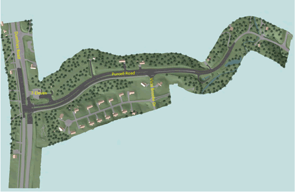
Figure 22: 3-D model plan view of RSA study area on Purcell Road
Key RSA Findings and Suggestions
The RSA team evaluated existing conditions as well as the proposed 90% design. A summary of key safety issues investigated with the assistance of the 3-D model and suggested mitigating actions is presented in Table 7.
Table 7 : Key safety issues and suggested mitigating actions
| Selected Safety Issue | Suggested Action |
|---|---|
|
Speed The realignment of Purcell Road between Dumfries Road and Vista Brooke Drive significantly straightens and widens the roadway, potentially increasing speed. |
Lane Width Reduce the lane width from 12 feet to 11 feet throughout the project corridor by adjusting the placement of edgeline striping. Optical Speed Bars Apply optical speed bars through severe curves. Optical speed bars are transverse stripes spaced at gradually decreasing distances along the edgelines of a curve. Raised Pavement Markers (RPMs) Install snowplowable RPMs through the curves in the vicinity of Rocky Brooke Court. RPMs are reflective devices that provide additional guidance through alignment changes, particularly during low-light conditions. |
|
Convenience Store Access A highly-recognizable convenience store is located in the northeast quadrant of the intersection of Purcell Road/Dumfries Road. The proposed design provides a right-turn lane into the convenience store property from Purcell Road; however, the distance between the access point and the intersection is relatively short. The lane use at the intersection is left only and right only. The situation may arise where an approaching motorist maymistakenly use the right-turn lane for the convenience store as the right-turn lane for access to northbound Dumfries Road. |
Supplemental Signage Install a supplemental "AT SIGNAL" sign (R10-31P) to the diagrammatic lane use sign assembly in advance of the intersection of Purcell Road/Dumfries Road. Pavement Marking Messages Change the spacing of the lane use pavement marking messages on Purcell Road. The placement of this particular marking may indicate to some motorists to make a right turn to the convenience store. Changing the spacing of the pavement marking messages may reduce confusion and unnecessary lane changes. Offset Offset the right-turn lane with pavement markings at the convenience store access. The offset pavement markings would further reinforce that the right lane is for the convenience store access. Sight distance improvements could also be expected for vehicles exiting the store, as offsetting the rightturning traffic would increase visibility of motorists destined for Dumfries Road. |
|
Two-Lane/Four-Lane Transition The proposed design transitions from a 4-lane cross section to a 2-lane cross section in the vicinity of Vista Brooke Drive. In the eastbound direction, the transition is accomplished by using the rightmost travel lane as a rightturn "trap" lane into the Vista Brooke community. |
Transition Begin the lane transition west of Vista Brooke Drive instead of at the intersection. Create a lane drop on Purcell Road in the eastbound direction by striping out a section of the rightmost lane west of Vista Brooke Drive and installing appropriate signing (W4-2, W9-1, W9-2) and lane reduction arrow pavement markings. Downstream of the lane drop, use the rightmost lane pavement as a right-turn lane into Vista Brooke Drive. The right-turnlane "pocket" instead of the right-turn lane "trap" will more clearly indicate the intended use of the lane (i.e., accessing Vista Brooke Drive). |
One corridor-wide observation was the significant elevation difference between the edge of pavement and the roadside. These areas pose a safety hazard to vehicles drifting off the paved surface. Although shoulder stabilization and roadside rehabilitation are included in the proposed design plan, this safety issue could be considered for immediate attention by maintenance personnel. As a result of this RSA, the roadside drop-offs were immediately addressed, as shown in Figure 23.

Figure 23: Shoulder with edge drop-off before (L) and after (R) RSA was conducted. The edge drop-off was immediately corrected following the RSA workshop
Benefits of the 3-D Visualization
Three-dimensional visualization was an important element in demonstrating the proposed changes to the public. Since the project passed directly behind houses and by a neighboring community, it was important to be able to show the impacts on homeowners and the adjacent community. The extents of the proposed roadway widening and realignment as well as landscaping and fencing placements were all critical to demonstrating the overall project impact. Furthermore, realistically depicting existing features, such as the highly-recognizable convenience store (see Figure 24), was key to building confidence in the accuracy of the model. Ultimately, the model was utilized in a public meeting to illustrate the project to all stakeholders. This included a video of the various "drive through" viewports that was continuously looped on a computer screen prior to the formal meeting.
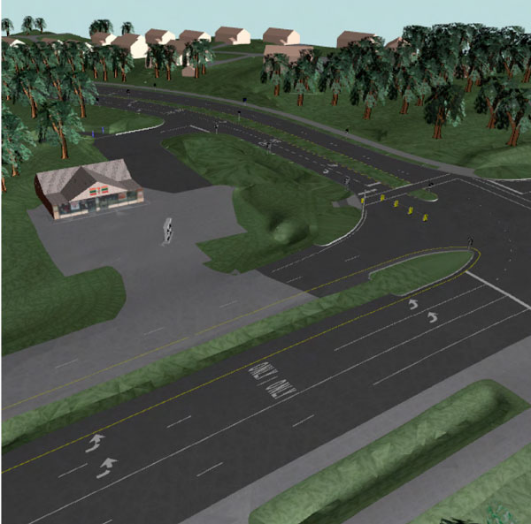
Figure 24: Bird's-eye view of the convenience store and the neighborhood in the background as seen from west of Dumfries Road
Having the ability to navigate through the corridor and observe different views was helpful in understanding the comprehensiveness of the proposed design. Looking at the project from a bird's-eye view provided a better understanding of the design, especially the roadside features that were not easily understood when looking at a 2-D plan or even the "drive through" model view (see Figure 25).
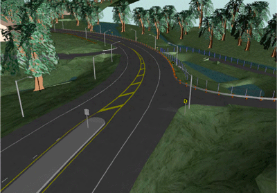
Figure 25: Bird's-eye view of realigned section of road at the west end of the project
"Driving" the corridor using the model was also critical to identifying potentially confusing signing and pavement markings, as well as driveway access concerns. A review of traditional 2-D roadway plans would not have provided the same insights as the 3-D model. For example, the placement of pavement markings combined with the curve of the road and location of trees may confuse drivers traveling westbound on Purcell Road approaching the convenience store and the intersection with Dumfries Road as to the proper lane placement based on their desired destination (see Figure 26).
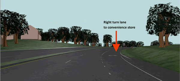
Figure 26: View along westbound Purcell Road approaching convenience store and Dumfries Road
In general, RSA team members commented that the 3-D model "brought the design to life". Even those members who have been reading design plans for their professional careers appreciated the usefulness of the model, as it helped them to more accurately understand the intended project outcome.
RSA No. 4-Western Terminus of Proposed Mid County Parkway, Riverside County, California
| Project Overview | |
| Project Location | Interstate 215 from Nuevo Road to Harley Knox Boulevard |
| Planned Improvements |
|
| Project Environment | Suburban |
| Project Design Stage | Preliminary (40 to 80%) |
| Project Owner(s) | Riverside County Transportation Commission, California Department of Transportation |
| RSA Overview | |
| Date of RSA | January 31 - February 2, 2012 |
| RSA Stage(s) | Design stage and RSA of existing roads |
| RSA Team | Representatives from California Department of Forestry and Fire Protection, California Department of Transportation, California Highway Patrol, City of Perris, Federal Highway Administration, Riverside County Transportation Commission, and Vanasse Hangen Brustlin, Inc. |
| 3-D Visualization Overview | |
| Level of Effort | 120 hours were expended to build 3-D model. |
| Information Provided by Designers |
|
Project Background
The objective of this study was to complete an RSA of a planned interchange between an Interstate highway and a multi-lane, limited-access facility (called the Mid County Parkway) in the City of Perris, Riverside County, California. The Mid County Parkway was proposed to help alleviate existing congestion and to meet the projected regional traffic demands by providing a critical new east-west thoroughfare in Riverside County. As currently designed, Mid County Parkway will be 16 miles long and connect I-215 in Perris to State Route (SR) 79 in San Jacinto. The RSA study area is shown in Figure 27.
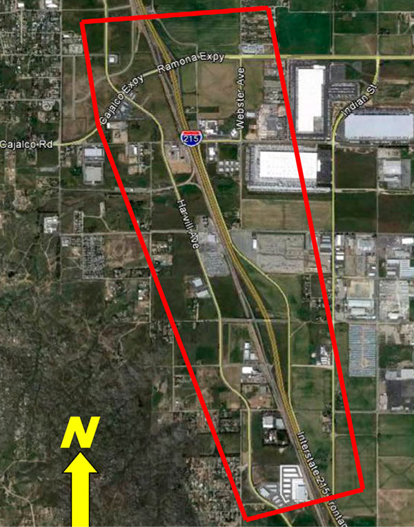
Figure 27: Study area for Mid County Parkway RSA
Following multiple rounds of environmental analyses, engineering studies, and public meetings, a preferred alignment was identified for the Mid County Parkway. Known as "Alternative 9," this option included a freeway-to-freeway interchange between Mid County Parkway and I-215 to be located between Placentia Avenue and Nuevo Road (see Figure 28). The interchange would constitute the western terminus of Mid County Parkway.
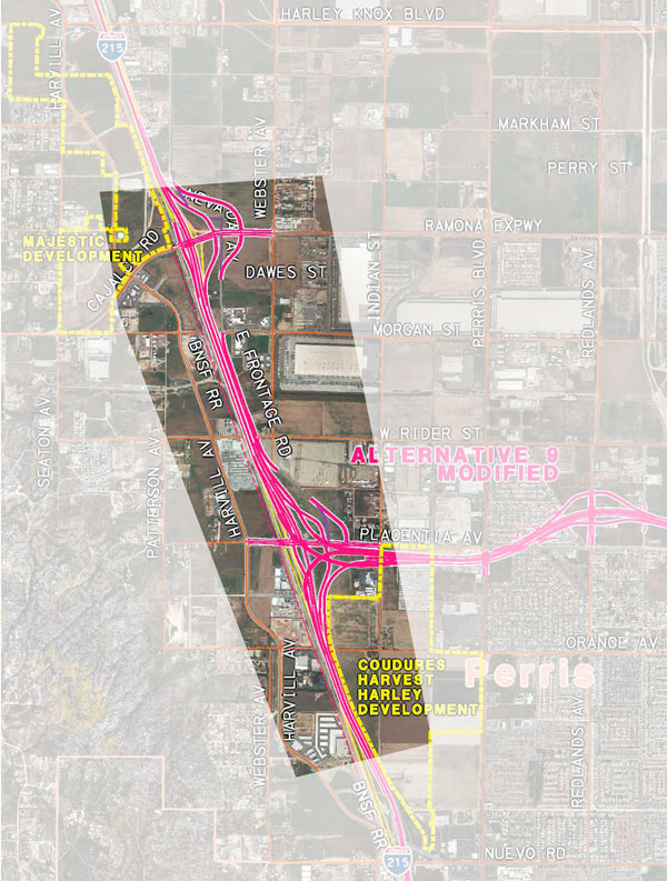
Figure 28: Preferred alignment (Alternative 9) for the western terminus of Mid County Parkway
The RSA and the 3-D visualization effort concentrated primarily on the following areas:
- The proposed freeway-to-freeway connection between Mid County Parkway and I-215, with emphasis on the westbound-to-northbound movement
- A newly-proposed interchange at I-215 and Placentia Avenue
- Interchange improvements at I-215 and Cajalco Expressway/Ramona Expressway
- The proposed realignment of the I-215 East Frontage Road
Information used by the RSA team to conduct the review included the following:
- Crash data (October 2007 - September 2010; for I-215 from D Street to Van Buren Boulevard)
- Existing (2010) average annual daily traffic (AADT) and select peak hour counts
- Projected (2040) AADT and select peak hour movements
Key RSA Findings and Suggestions
A summary of selected safety issues and suggested mitigating actions is presented in Table 8.
Table 8: Summary of select safety issues and suggested actions
| Selected Safety Issue | Suggested Action |
|---|---|
|
Inadequate street lighting and delineation Vertical crest curve at Placentia Ave. bridge overpass is unlit and obstructs driver visibility. New series of reverse horizontal curves added to presently unlit Frontage Rd. Potential for nighttime confusion for NB drivers on Frontage Rd. due to |
Provide street lighting at and near the bridge. Enhance delineation at the newly-introduced horizontal curves. |
|
Visibility concerns Close proximity of SB exit ramps to bridge structures will restrict sight distance of right-turning traffic. Safety issues related to the proposed dual right-turn lanes:
With up to six lanes along I-215, types of guide signs currently in use may be obscured and, therefore, largely ineffective. |
Consider prohibiting right turns on red from the SB exit ramps. Install sign bridge structures to allow all critical guide signage to be installed above the Interstate through lanes. |
|
Roadside safety Currently no detailed plans for application of guardrail, median barrier, etc. in conjunction with proposed improvements. |
Identify the specific applications of traffic safety systems, particularly in light of numerous bridge support and sign structures, grading limits, etc. |
|
Capacity and operational concerns Close interchange spacing (less than one mile) along I-215 combined with high entering/exiting volumes and expected extensive weaving maneuvers. |
Consider revisiting the traffic analysis by applying detailed assumptions regarding the lane selection and merge/ diverge behavior among drivers within the study corridor to ensure there will be adequate capacity in peak hours. |
|
Wayfinding Development of in-depth signing and pavement marking plans are critical to overall project and should commence as soon as possible. Close interchange spacing combined with high speeds and projected high volumes will require drivers to process information and make decisions very quickly; therefore, application and placement of guide signs will have huge impact on safety and operations within the corridor. |
Develop detailed signing and marking plans. Consider incorporating diagrammatic and lane-assigning overhead signs to encourage drivers to change lanes in advance of the merge/diverge conditions. |
Benefits of the 3-D Visualization
The review of the 3-D model supported a comprehensive approach to the planning and design of the project-one that included consideration of key components of the roadway environment, such as wayfinding signs, pavement markings, and roadside barriers. Because of the scale of the Mid County Parkway project, it was not feasible to build a 3-D model that would incorporate all of the proposed roadway improvements. Based on conversations between the project team, FHWA, the project owners, and others, it was decided that the model would focus primarily on northbound movements along I-215 at Mid County Parkway, Placentia Avenue, and Cajalco Expressway/Ramona Expressway. The area selected for 3-D visualization was considered critical to the RSA in large part because of the proximity among interchange ramps, which is characterized by the following:
- Approximately 1,000 ft (0 2 mi) between the northbound exit ramps at Mid County Parkway and Placentia Avenue;
- Approximately 1,200 ft (0 2 mi) between the northbound entrance ramps from Placentia Avenue and Mid County Parkway; and
- Approximately 3,700 ft (0 7 mi) between the northbound entrance ramp from Mid County Parkway and the northbound exit ramp at Cajalco Expressway/Ramona Expressway
This close ramp spacing creates an environment in which a multitude of merging and weaving maneuvers can be expected over a short distance. Figure 29 illustrates the proposed lane configurations and key projected peak hour volumes along northbound I-215 within the study area.
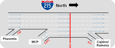
Figure 29: Illustration of proposed lane configurations and key 2040 AM peak hour volumes for NB I-215
Vehicles entering I-215 from Placentia Avenue must merge into the four mainline lanes, while the two lanes coming from Mid County Parkway will join I-215 to create a six-lane cross section (see Figure 30). The rightmost lane will become an exit-only lane onto Cajalco Expressway/Ramona Expressway, with the adjacent lane allowing vehicles to either exit or continue north along I-215.
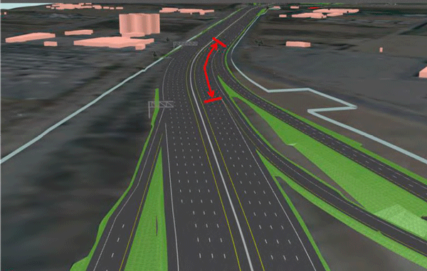
Figure 30: Image from 3-D model showing proximity of northbound I-215 entrance ramps from Placentia Ave and Mid County Pkwy
By traveling along the northbound paths within the model, the RSA team gained a realistic sense of what the proximate ramp connections would look like upon construction. It was noted that Caltrans has been known to use 2,200 vehicles per lane per hour as an upper limit of "stop-and-go" capacity along its freeways. Evenly dividing the total projected I-215 volume across the lanes resulted in per-lane volumes below capacity; however, if the projected volumes were assigned to the proposed cross section based on consideration of expected driver behavior and interactions and not through an even distribution, then the potential for certain lanes to become over-saturated may be realized. From this discussion, the RSA team made three recommendations:
- The development of detailed signing and pavement marking plans should commence early in the design process and not be left as a final step.
- Diagrammatic and lane-assigning signs should be included in the signing plan to encourage drivers to maneuver into the appropriate lanes well before they encounter the merge/diverge conditions. (Some examples of such signs are provided in Figure 31 and Figure 32).
- Consider the reassessment of per-lane capacity by applying human factors considerations to the lane selection and merging/diverging behavior in this segment of I-215.

Figure 31: Mock up of freeway guide signs on Mid-County Parkway
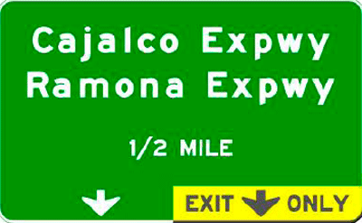
Figure 32: Mock up of exit sign along I-215
Another concern highlighted by the 3-D model was that the sign types currently in use along I-215 (see Figure 33) may be obscured by heavy vehicles and, therefore, largely ineffective in delivering information to drivers in the leftmost lanes. The rendering of the driver's vantage emphasized the vastness of the cross section and supported the notion of diminished value of roadside signs to left-lane drivers due to the distance from their vehicles to the right side of the road (see Figure 34). Therefore, it was recommended that the designers consider the installation of sign bridge structures to allow all critical guide signing to be placed above the Interstate through lanes, which will promote sign visibility to drivers in all of the travel lanes.
Figure 33: Photo of existing freeway guide sign in use along I-215
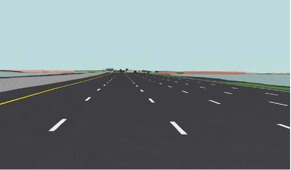
Figure 34: 3-D image showing wide cross section of I-215 and distance from left lanes to the right edge of the roadway
The 3-D model also helped identify the potential for nighttime confusion among northbound drivers on the I-215 east frontage road. Drivers here will be looking almost directly at the proposed traffic signal at the realigned northbound I-215 exit ramp at Ramona Expressway. Figure 35 and Figure 36 show the vantage of the northbound driver in plan view and in 3-D, respectively. This perspective could lead drivers to expect that they will be following a path toward the ramp signal and not curving toward the right, as per the proposed designs. The concern became much more apparent to the RSA team by virtually "driving" the frontage road in the 3-D model than it would have by only conducting a review of the 2-D roadway design plans.
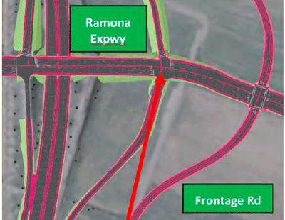
Figure 35: Vantage of NB driver on frontage road as seen in plan view
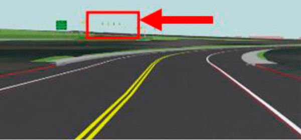
Figure 36: 3-D Image from 3-D model showing vantage of NB driver on frontage road
Just as the 3-D model proved valuable in its ability to illustrate the vertical qualities of the traffic signal, it also helped the RSA team to visualize the impacts of other 3-D features in the roadway environment. The proximity of the southbound I-215 exit ramps to the bridge overpasses at Cajalco Expressway/Ramona Expressway and Placentia Avenue was noted as a safety concern. This closeness gives the bridge structures the potential to obstruct sight distance for drivers looking to turn right on a red signal indication. (See Figure 37, Figure 38 and Figure 39 for supporting images from the 3-D model.) This example also highlights the benefits of including as much detail in the model as possible, as the more accurate information that can be input into the model, the more accurate assessment that can be made of it on the total design-in this case, the impacts of the bridge design on various users of the roadway.
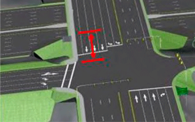
Figure 37: Image from 3-D model showing proximity of bridge structure to ramp terminus
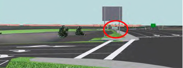
Figure 38: Image from 3-D model showing potential for overpass structure to obstruct sight distance of drivers at SB exit ramp
In the end, 3-D visualization was instrumental in the RSA of the western terminus of Mid County Parkway. By bringing the planned complex interchange to life, the multidisciplinary RSA team was able to travel the conceptual roadway segments and view them from the vantage of prospective users. The model played an integral role in both the discussions among team members and those between the team and the stakeholders by providing a visual representation to the abstract design. Additionally, 3-D visualization helped bring to light issues that may have otherwise gone unnoticed from a review of only the 2-D plans, such as the concern about the traffic signal vantage for drivers on the east frontage road.

Figure 39: Image from 3-D model showing closeness of interchange ramps and multilane cross section

