
J. Sterling Jones Hydraulics Research Laboratory Overview
National Hydraulics Research Program
Laboratory Purpose
The J. Sterling Jones Hydraulics Research Laboratory at the Federal Highway Administration’s (FHWA’s) Turner-Fairbank Highway Research Center is part of the Office of Infrastructure Research and Development. The laboratory is responsible for research related to the impacts of flooding on highway infrastructure.
One major impact of flooding is bridge scour. Bridge scour is the leading cause of bridge failures in the United States (approximately 25 to 30 bridges per year). Thousands of bridges are listed as "scour critical" in the National Bridge Inventory (NBI). FHWA's scour design methods are overly conservative because of the numerous uncertainties associated with scour design. More research is needed to better understand bridge scour and to develop improved scour design tools for practitioners.
The J. Sterling Jones Hydraulics Research Laboratory has conducted research on bridge scour and other highway hydraulics phenomena for more than 35 years. The laboratory is a state-of-the-art research facility with instrumentation, robotics, testing apparatuses, flumes, and computational fluid dynamics (CFD)/computational structural mechanics (CSM) capabilities that have improved significantly over the past several years. The laboratory conducts research related to the National Hydraulics Research Program's functional areas and provides the capabilities and experience to conduct physical experiments and CFD modeling on a variety of issues involving water flow at or near the Nation's highway infrastructure.
CFD/CSM experiments superseded physical testing by a large margin in recent years and this trend will continue. The laboratory's vision is to improve testing efficiency by automating zones within the lab using mobile robotics. The goal for the next couple of years is to continue conducting high quality research, advance trends in CFD/CSM modeling, and further automate testing facilities.
CFD modeling is conducted through collaboration with the Department of Energy’s Argonne National Laboratory Transportation Research and Analysis Computing Center. This collaboration allows access to high-performance cluster computing. Access to these clusters enables the J. Sterling Jones Hydraulics Research Laboratory to solve highway hydraulics research problems more efficiently.

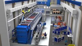
Figure 1. The FHWA's J. Sterling Jones Hydraulics Research Laboratory at the Turner-Fairbank Highway Research Center (Click to view larger image).
Research Program
The Hydraulics Research Program is a part of the National Hydraulics Research Program and coordinates research with the National Hydraulics Team (NHT), including the program office (HQ), FHWA Resource Center, and Federal Lands Highway offices. The research program studies problems related to the six functional areas that were developed by NHT:
- Hydrology and Extreme Weather
- Highway Drainage/Pavement Hydraulics
- Culvert Hydraulics
- Bridge Hydraulics
- Scour, Steam Stability, and Scour Protection (Countermeasures)
- Coastal Highways
Laboratory Description
The J. Sterling Jones Hydraulics Research Laboratory is divided into seven zones for better laboratory management, maintenance, and capital improvements. The zones include:
- Zone 1 – Multifunctional flume system
- Zone 2 – Force balance flume system
- Zone 3 – In situ scour testing device (ISTD), lab drill rig
- Zone 4 – Lab soil erosion testing devices
- Zone 5 – Particle image velocimetry (PIV), lasers, and cameras
- Zone 6 – Laboratory office and 3D printing
- Zone 7 – Laboratory machine shop
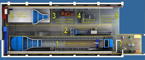
Figure 2. J. Sterling Jones Hydraulics Research Laboratory zones.
Recent Accomplishments and Contributions
Publications
Recent publications include technical reports documenting NextScour case studies for Michigan and North Carolina Departments of Transportation (DOTs). NextScour is FHWA’s next-generation scour research initiative with the goal of improving scour analysis and providing more accurate scour depth estimates for bridge foundation design.
J. Sterling Jones Hydraulics Research Laboratory Publications
| Publication Title | Publication Number | Year |
|---|---|---|
| NextScour Case Study: The I–6064/I–95 Bridge Replacements Over the Lumber River in Lumberton, NC | FHWA-HRT-24-038 | 2024 |
| ISTD Field Demonstration Factsheets | 2024 | |
| NextScour Case Study: The Lafayette Avenue Bridge Over the Saginaw River in Bay City, Michigan | FHWA-HRT-23-014 | 2023 |
| Curb-Opening Inlet Interception on Grade TechNote | FHWA-HRT-22-061 | 2022 |
|
Pier Scour Estimation for Tsunami at Bridges |
FHWA-HRT-21-073 |
2021 |
|
Applying Engineered Logjams and Dolosse forStreambank Stabilization |
FHWA-HRT-21-028 |
2021 |
|
Hydraulic Considerations for Shallow Abutment Foundations |
FHWA-HIF-19-007 |
2018 |
|
Advanced Methodology to Assess Riprap Rock Stability At Bridge Piers and Abutments |
FHWA-HRT-17-054 |
2017 |
|
Hydraulic Performance of Shallow Foundations for the Support of Vertical-Wall Bridge Abutments |
FHWA-HRT-17-013 |
2017 |
|
Updating HEC-18 Pier Scour Equations for Noncohesive Soils |
FHWA-HRT-16-045 |
2016 |
|
Scour in Cohesive Soils |
FHWA-HRT-15-033 |
2015 |
|
Fish Passage in Large Culverts with Low Flow |
FHWA-HRT-14-064 |
2014 |
|
Submerged Flow Bridge Scour Under Clear Water Conditions |
FHWA-HRT-12-034 |
2012 |
|
Pier Scour in Clear-Water Conditions with Non-Uniform Bed Materials |
FHWA-HRT-12-022 |
2012 |
Technical Assistance
| Agency | Fiscal Year | Subject |
|---|---|---|
| MDOT(MS) | FY23/24 | TPF-5(461). Conducted CFD and 2D modeling and soil erosion testing of “Yazoo” clays for I-20 over Lynch Creek in Jackson, MS. |
| FDOT | FY23 | Conducted CFD and physical modeling of riprap countermeasures for the Mathews Bridge in Jacksonville, FL, including an investigation of geotextile sand tubes for protection from edge failure. |
| PennDOT | FY21/22 | TPF-5(461). Performed soil erosion testing for SR-551 bridge replacement over Sugar Creek. |
| NCDOT | FY21/22 | TPF-5(461). Conducted CFD and 2D modeling and soil erosion testing for I-6064/I-95 bridge replacement over the Lumber River in Lumberton, NC. |
| MDOT(MI) | FY21/22 | TPF-5(461). Conducted CFD and physical modeling and soil erosion testing for Lafayette Avenue Bridge replacement over the Saginaw River in Bay City, MI. |
| CDOT | FY21 | TPF-5(461). Performed soil erosion testing for US-40 Bridge over the Agate Creek. |
| ADOT | FY20 | TPF-5(461). Conducted CFD modeling and soil erosion testing for SR-80 over the San Pedro River. |
| USACE-ERDC | FY19 | Designed, fabricated, and installed two instrumentation robotics systems for the USACE-ERDC Cognitive Ecology and Ecohydraulics Laboratory |
| USACE-LA District | FY19 | Pier extension and guide wall design alternatives to mitigate local scour risk for the Burlington Northern and Santa Fe (BNSF) Railroad Bridge over the Santa Ana River downstream of Prado Dam in Riverside County, CA |
| SCDOT | FY18 | Hydraulic study of SCDOT catch basin type 25 (CB25) |
| MDOT(MI) | FY17 | Soil sample erosion testing for M–20 Bridge over the Tittabawsee River |
| Western Federal Lands | FY17 | Testing engineered log jams for roadside erosion protection for a proposed project next to Hoh River Olympic National Park in Washington State |
| MD SHA | FY16 | User Guide to assist HY–8 users in the application of HY–8's low-flow capability for identifying zones of lower velocity during low flows in culverts |
| VDOT | FY16 | Improve design methodology for estimating scour in rock for abutments |
|
Caltrans |
FY15/FY16 | Scour Study for the Feather River Bridge over the Feather River in Sutter County, CA |
|
Caltrans |
FY15/FY16 | Scour Countermeasure Study for the Middle Fork Feather River Bridge over the Middle Fork of the Feather River in Plumas County, CA |
FY: fiscal year; FDOT: Florida Department of Transportation; PennDOT: Pennsylvania Department of Transportation; TPF: Transportation Pooled Fund; NCDOT: North Carolina Department of Transportation; MDOT: Mississippi or Michigan Department of Transportation; CDOT: Colorado Department of Transportation; ADOT: Arizona Department of Transportation; USACE: U.S. Army Corps of Engineers; USACE - ERDC: USACE’s Engineer Research and Development Center; SCDOT: South Carolina Department of Transportation; MD SHA: Maryland State Highway Administration; VDOT: Virginia Department of Transportation; Caltrans: California Department of Transportation.
Other Accomplishments
In Situ Scour Testing Device Patent: Patent No.: 9,322,142 (Issue Date: Tuesday, April 26, 2016).
Laboratory Capabilities and Equipment
For detailed explanations of the capabilities and equipment at the J. Sterling Jones Hydraulics Research Laboratory, select the content below. These pages include specifics on the laboratory zones and the Advanced Computing Center.
Laboratory Services
The laboratory is capable of providing the following support services:
- Technical assistance.
- CFD modeling.
- Flume testing.
- In situ/ex situ erosion testing.
- Automated testing.
- Mechatronics support.
- Research oversight.
- 3D printing and laser cutting.
Zone 1 – Multifunctional Flume System (MFS)
Zone 2 – Force Balance Fume System (FBF)
Zone 3 – In situ Scour Testing Device (ISTD) – Lab Drill Rig
Zone 4 – Laboratory Soil Erosion Testing Devices
Zone 5 – Particle Image Velocimetry (PIV), Lasers, and Cameras
Zone 6 – Laboratory Office and 3D Printing
Zone 7 – Laboratory Machine Shop
Zone 1 – Multifunctional Flume System (MFS)
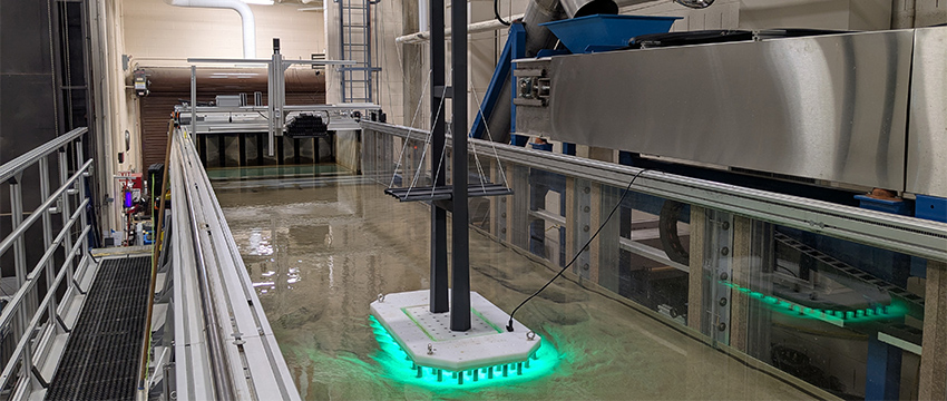
The MFS features a 90-foot-long by 13-foot-wide tiltable working platform for experimental setups. Channel sections of 3- or 6-foot wide can be mounted on the working deck. Both channel section alternatives include a 27-foot-long sediment recess test section. If needed, other hydraulic structures such as culverts, pipes, and drainage systems can be installed and tested. The flume system also includes a 27-foot-long flow inlet headworks and a carefully designed outlet section that includes a sediment trap. The sediment recirculating system, which is the only one of its kind in the United States, consists of an inclined auger, conveyor belt, and sediment infeed hopper. Diaphragm pumps push sediment from the infeed hopper into the flume through computationally-optimized and 3D-printed infeed nozzles located at the bottom of a specially-designed channel section. This sediment recirculation capability allows for much more realistic river flow modeling. The pump discharge capacity of the MFS is 30 cubic feet per second (ft3/s). An automated instrumentation carriage and industrial robot carriage system hold sensors needed to measure flow and sediment transport/scour data, and to assist with the setup of experiments. The main purpose of the experiments in the MFS is to calibrate computational fluid dynamics (CFD) models for further analysis and development of guidelines.

Figure 1. Elevated view of the MFS (Click to view larger image).

Figure 2. View of the MFS’s industrial robot carriage system (Click to view larger image).
Zone 2 – Force Balance Flume System (FBF)
The force balance flume is 36 feet long and 15 inches wide. In this configuration, a discharge rate of over 3 ft3/s can be achieved. An industrial robotic arm is utilized on the FBF to hold sensors for measuring flow properties and to act as a temporary force balance for the study of hydrodynamic loads on structures until a new force balance tower is installed. The proposed force balance tower will also be used to study hydraulic erosion forces on 3D-printed bridge foundation scour forms. The main purpose of the FBF is to perform high-precision force measurement experiments to calibrate CFD simulations. The goal of these experiments is researching and analyzing hydrodynamic loads/forces responsible for scour and erosion around bridge foundations in order to improve scour prediction estimates for the new scour design vision.

Figure 3. The Force Balance Flume in the Hydraulics Lab (Click to view larger image).
Zone 3 – In-situ Scour Testing Device (ISTD) – Laboratory Drill Rig
The ISTD is an advanced system designed to measure the erosion resistance of fine-grained cohesive soils directly in the field. It features an innovative erosion head that, when inserted into a standard drill casing, can direct a horizontal radial flow across the surface of the soil resulting in erosion. The erosion resistance is measured in terms of a critical shear stress, which when coupled with the decay of hydraulic shear with scour depth, is the basis of FHWA's new scour vision for improving the accuracy of future bridge scour estimates.
The laboratory hosted a series of field demonstrations in States across the country to promote the technology and improve the ISTD system's technology readiness level. A photo showing the typical layout of the equipment at a demonstration is shown in figure 4.

Figure 4. The setup of the ISTD equipment in the field for a demonstration.
A simplified “portable” scour testing device (PSTD) was recently developed in the lab and introduced to the field demonstrations that allows the tests to be conducted at ground level in a reduced footprint to improve testing efficiency.

Figure 5. The simplified PSTD setup in the field. (Click to view larger image.)
Zone 4 – Laboratory Soil Erosion Testing Devices
Multiple devices and tools are utilized in this laboratory zone including the ex-situ scour testing device laboratory (ESTD) and various soil preparation and geotechnical testing apparatuses.
Soil Compaction Station
The soil compaction station reproduces lab soil samples that have similar strength to field soils. An intelligent industrial robot featuring a 7-axis robotic arm and mobile platform is programmed to carry soil samples between the compaction station and the various testing devices while utilizing sensors to avoid obstacles.

Figure 6. An industrial robot prepares to place soil samples in the compaction station.
Ex-Situ Scour Testing Device (ESTD)
The ESTD measures the erodibility of a cylindrical soil specimen under well-controlled flow conditions. It has an overall dimension of 15-feet long, 6-feet wide, and 5.3-feet high. Its rectangular testing channel has a dimension of 3-feet long, 4.7-inch wide, and 0.75-inch high. The maximum flow rate in the ESTD is 0.5 ft3/s, which translates to a maximum average flow speed of 20 ft/s in the testing channel. The ESTD features an innovative shear stress sensor that can instantaneously measure the bed shear stress during the erosion process. The system can accommodate a 1-foot-long field soil sample in a Shelby tube with a 3-inch outer diameter. The soil can be automatically pushed up by a hydraulic piston as the erosion progresses. The extrusion is controlled by quasi-instantaneous detection of the soil surface change using an underwater laser scanner held by an industrial robot.
Soil erosion resistance testing is a part of the new scour design vision and is needed to determine the scour depth limit state. The vision of zone 4 is to develop and demonstrate a fully automated soil erosion resistance testing laboratory which utilizes a robotic assembly line that can be deployed in the field.

Figure 7. The ex-situ scour testing device (ESTD).

Figure 8. The robot inserts a soil sample into the ESTD.
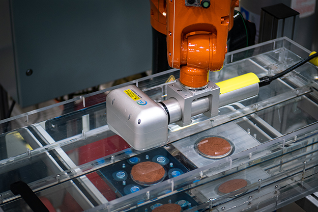
Figure 9. The laser scanner measuring the surface of a soil sample in the ESTD.
Zone 5 – Particle Image Velocimetry (PIV), Lasers, and Cameras
Particle Image Velocimetry (PIV) is an optical method of flow visualization used for many research activities in the J. Sterling Jones Hydraulics Research Laboratory. It is used to obtain instantaneous velocity measurements and related flow properties. The flow is seeded with tracer particles that, for sufficiently small particles, are assumed to faithfully follow the flow dynamics. The flow with entrained particles is illuminated so that particles are visible. The motion of the seeding particles is used to calculate speed and direction (the velocity field) of the flow being studied.
The J. Sterling Jones Hydraulics Research Laboratory's PIV system can be used for 2D-2 Components and 2D-3 Components Time Resolved PIV (TPIV). The Laboratories Litron LPY laser has a pulse energy of 50mJ and consists of two parallel laser systems, each capable of creating 200 pulses per second, that allow for the usage of TPIV. Special laser optics can create light sheets that are from 1- to 3-mm thick, illuminating the cross section of the flow that needs to be visualized. Hollow glass spheres (with a diameter of 10 to 110 microns) covered with silver oxide are used as tracer particles. High-speed cameras are utilized to detect the motion of the particles and to measure the velocity flow field.

Figure 10. The Litron LPY laser illuminating the ISTD erosion head for a PIV experiment.
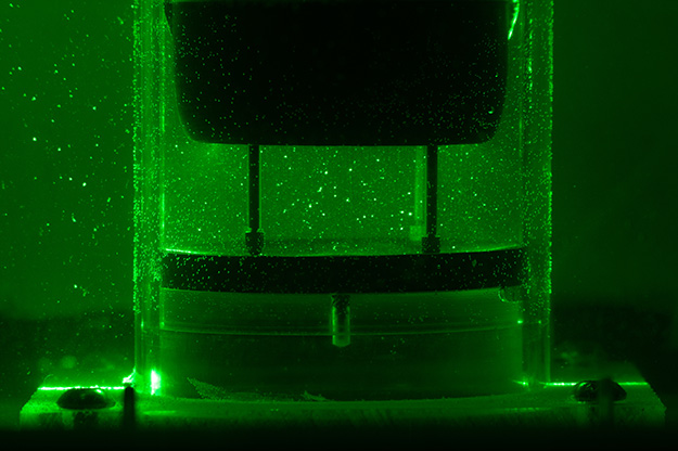
Figure 11. Tracer particles around the erosion head allow for flow visualization.
Zone 6 – Laboratory Office and 3D Printing
The laboratory has an office designed as a collaboration and modeling space for the lab personnel. The second floor includes an advanced computing center where experienced CFD specialists prepare computer simulations that are then sent to Argonne National Laboratory’s (ANL’s) Transportation Analysis Research Computing Center (TRACC), where multicore clusters run the simulations. A conference room for collaborative discussions is on the second floor. An Advanced Engineering Hub is where lab personnel perform calculations and work immersed in the lab environment with noise- and climate-control to optimize performance. Multiple 3D printers are located both on the first and second floors of the office. These printers are utilized to create bridge models, sensor mounts, presentation models, and other essential functions.

Figure 12. Lab conference room with Fortus 3D printer in far-left corner.
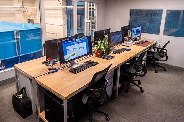
Figure 13. Advanced Computing Center.

Figure 14. Advanced Engineering Hub.
Zone 7 – Laboratory Machine Shop
The laboratory also has its own machine shop where various tools can be accessed. Basic tools such as hex-head wrenches, pliers, fasteners, screws, etc., are stored here. Additionally, the machine shop is equipped with multiple milling machines and various saws that can be utilized to prepare experiments and build structures. A new addition to the machine shop is a state-of-the-art laser cutter that is being used to help prepare bridge models as well as precisely resized and shape compatible materials.
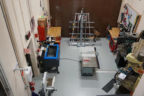
Figure 15. Laboratory Machine Shop.
J. Sterling Jones Hydraulics Research Laboratory Advanced Computing Center
The Federal Highway Administration’s (FHWA’s) J. Sterling Jones Hydraulics Research Laboratory’s numerical modeling is performed at the Transportation Research and Analysis Computing Center (TRACC) cluster at the Argonne National Laboratory (ANL). This modeling is completed through remote access using high-speed internet (I2) and collaboration. Since the beginning of the collaboration in 2008, computational fluid dynamics (CFD) modeling for conducting research studies has exceeded physical testing in the laboratory. Hundreds of numerical experiments are running round the clock on the ANL/TRACC clusters to solve highway hydraulics issues. From 2017 to 2024, CFD modeling will increase to 70 percent and experimental work will reduce to 30 percent in the laboratory.
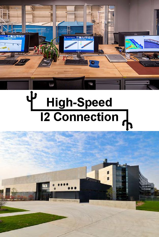
Figure 1. J. Sterling Jones Hydraulics Research Laboratory Advanced Computing Center connected to ANL/TRACC.
Argonne National Laboratory (ANL) Transportation Research and Analysis Computing Center
The Transportation Research and Analysis Computing Center (TRACC) was established in October 2006 through a legislative grant. The technical objectives of this original grant included the establishment of a high-performance computing center for use by U.S. Department of Transportation (USDOT) research teams, including those from ANL and university partners. These advanced computing and visualization facilities are used for the conduct of focused computational research and development programs in areas specified by the USDOT. As part of the original project, a supercomputing user facility was established, with full operations beginning in February 2008.
The set of research and development activities identified by USDOT included:
- Computational structural mechanics and methods for analysis and optimum design of safety structures and analysis of transportation-related infrastructure.
- Computational fluid dynamics for hydraulics and aerodynamics research.
- Traffic modeling and simulation and emergency transportation planning.
- Multidimensional data visualization.
These transportation research and demonstration projects focused on (1) the exchange of research results with USDOT and the private sector and (2) collaboration with universities to foster and encourage technology transfer.
The essential resources for transportation infrastructure research and analysis at TRACC include the high performance computing (HPC) clusters and expert staff in the areas of computational fluid dynamics (CFD) and computational structural mechanics (CSM). At present, TRACC has two HPC clusters. The five-year-old Phoenix cluster is a customized system consisting of 1024 cores on 128 compute nodes, each with two quad-core AMD Opteron CPUs and 8 GB of RAM; a DataDirect Networks storage system consisting of 180 TB of shared RAID storage; a high-bandwidth, low-latency InfiniBand network for computations; and a high-bandwidth gigabit Ethernet management network. The system also includes high-performance compilers and message passing interface (MPI) parallel processing libraries. Peak performance is about 4 Teraflops.
The new HPC Zephyr cluster became available for use in October 2012. Zephyr is a cluster with 92 compute nodes. Each node has two 16-integer cores, eight floating-point cores, AMD Interlagos 6273, and 2.3-Ghz CPUs. The majority of the nodes (88) have 32 GB of RAM; two nodes have 62 GB of RAM, and two nodes have 128 GB of RAM. Zephyr has a 40 GB/s InfiniBand interconnect between nodes, which is twice the speed of the Infiniband interconnects on the older Phoenix cluster. Zephyr also has a high-performance Lustre-based file system with 120 TB of formatted capacity. All nodes run an up-to-date CentOS Linux 6. TRACC researchers have developed methodologies and software applications to more easily run CFD and CSM software (STAR-CCM+ and LS-DYNA) on TRACC’s systems. The TRACC team has also held workshops and classes to train TRACC users in the use of these software packages for analysis of transportation infrastructure problems.
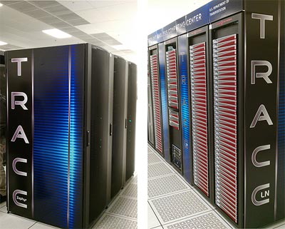
Figure 2. The photo shows the Zephyr (left) and Phoenix (right) computer clusters at the Argonne National Laboratory. Both clusters consist of 3,968 total cores on 220 total compute nodes with 32 cores each, a DataDirect Networks storage system, and a high-bandwidth network.
Last updated: Tuesday, August 26, 2025