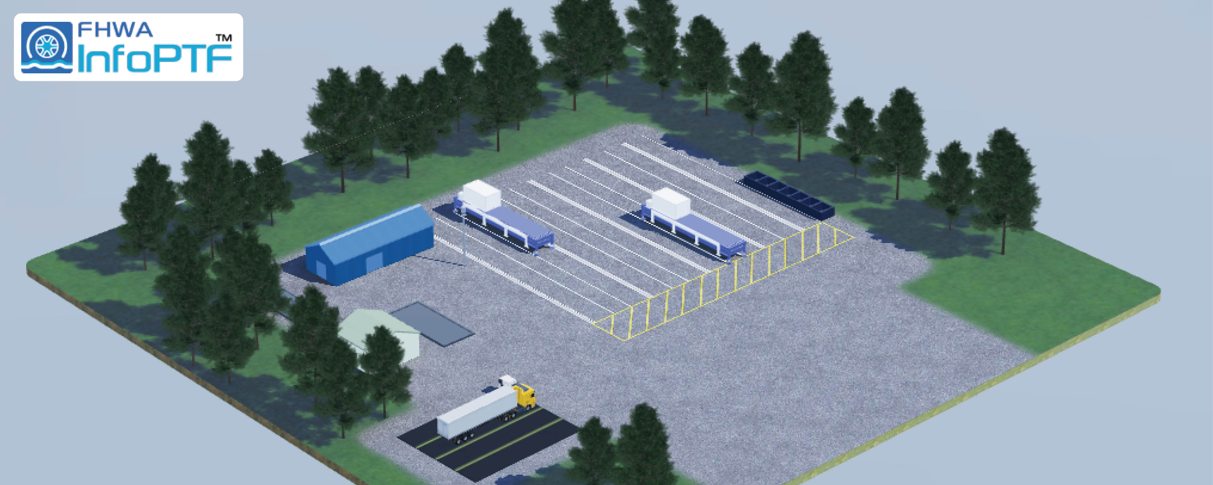
Nondestructive Evaluation (NDE) Roadmap Steel: Inservice Highway Infrastructure
Bridges have been designed using steel for more than 100 years due to steel’s superior versatility and excellent strength-to-weight ratio. Many steel bridges are still in service today, but they have far exceeded their original design life. As time passes, these bridges become more prone to deterioration and fatigue, causing asset owners to make decisions for retrofits or replacements based on the inspection reports or data captured. Currently, nondestructive evaluation (NDE) methods, other than visual inspection, are only deployed when there is a suspected issue. However, NDE allows for other opportunities for condition monitoring of steel bridges, such as detecting and investigating the root causes of problems and assessing their severity early in the asset’s lifecycle, which supports better decisionmaking.
This umbrella topic covers current best practices, return on investment, deterioration models, new technologies, and guidelines/standards for NDE methods used on steel bridges.
- Quality Assurance for Ancillary Structures (highway signs, signals, and luminaire support structures)
- Impact of Liftoff on Probability of Detection (POD) Using Eddy Current Arrays (ECA)
- NDE Requirements for Movable Bridges
- Crack Detection and Monitoring
- Measurement of Stresses in Anchor Bolt/Rods Using NDE
- Use of NDE for Measure Corrosion and Section Loss
- NDE for Fire and Impact Damage of Steel Bridges
- NDE for Load Rating and Stress Measurement
- Inspection of Cable Stay Anchorages
- Risk-Based NDE
- Bridge Pin Statement
- Enhanced Ultrasonic Reliability through Automation
- Exploring Automated and Advanced NDE from Other Industries for Steel Bridges
For optimum navigation, click "Expand All" above the list and then click on the link of desired section.
Ancillary structures, such as sign structures, light poles, high-mast lights, and signal supports, are ubiquitous throughout the Nation’s infrastructure and are an important asset for State agencies. Ancillary structure inspections generally consist of visual inspection with some consideration of traditional nondestructive evaluation (NDE) technologies, such as ultrasonic testing (UT), magnetic particle testing, dye-penetrant testing, or eddy current testing (ECT).(1) However, these traditional NDE technologies are challenging to implement effectively for ancillary structures due to the complex nature of some of the welded connections, the variety of materials used for ancillary structures, and the different coatings used for corrosion protection. For example, structures are sometimes galvanized, which can increase the complexity of NDE or render certain methods ineffective. Other structures may be formed from aluminum, presenting a different set of parameters for NDE than for steel structures. Some ancillary structures are formed from weathering steel, which significantly limits the inspectors’ ability to visually detect cracking.(2)
An additional challenge for inspecting ancillary structures is the sheer number of structures distributed throughout a given State agency’s jurisdiction. Practically speaking, an inspection technology must be rapidly implementable to be useful in any asset management strategy. Traditional NDE technologies are not practical for widespread use, due to requirements for cleaning and removal of coating, the complexity of welded connections, and the overall time required to implement the technologies. As a result, there is a need to develop practically implementable NDE technologies to inspect ancillary structures to provide the necessary tools for effective asset management and to ensure safety.
The primary damage modes affecting ancillary structures are corrosion-induced section loss and cracking resulting from fatigue loading, fabrication defects, or both. Section loss can be difficult to quantify because access is commonly limited. For example, many structures are tubular, such that access to the inside surface is unavailable. Cracking can be difficult to detect when structures are formed from weathering steel, when galvanizing is present, or when complex welded connections are used. Another significant issue for ancillary structures is the condition and performance of anchor bolts, which may not be properly installed and can fracture due to fatigue loading, section loss, or overload when forces are not distributed evenly between bolts.
Research Objective
This research’s objective is to develop implementable tools to improve inspectors’ ability to detect critical defects in ancillary structures. The critical defects include section loss due to corrosion, cracking, and anchor bolt condition and performance. Among these damage modes, UT to determine materials thickness is an available technology that can be used effectively in the field. This technology is also effective for assessing anchor bolt condition. However, for crack detection, existing technologies have limited practical effectiveness as noted previously. Methods with improved efficiency are needed.
The technology needed for crack detection in ancillary structures includes the following characteristics:
- Is capable of full field imaging.
- Is noncontact.
- Does not require coating removal.
- Is rapid to implement.
- Is effective on aluminum, galvanized steel, and weathering steel.
- Is effective on complex weld geometries.
Scope of Work:
- Conduct a literature review to identify the state of practice in ancillary structure inspection.
- Conduct a survey with state DOTs to identify specific requirements that need to be addressed in NDE of ancillary structures.
- Identify currently deployed NDE methods and existing gaps in these methods.
- Draft a final report documenting the results of the survey and literature review, providing comprehensive guidance towards the future direction of NDE in ancillary structures.
References
- Garlich, M. J., and E. R. Thorkildsen. 2005. Guidelines for the Installation, Inspection, Maintenance and Repair of Structural Supports for Highway Signs, Luminaires, and Traffic Signals. Report No. FHWA NHI 05-036. Washington, DC: Federal Highway Administration.
- Campbell, L. E., R. J. Connor, J. M. Whitehead, and G. A. Washer. 2020. “Benchmark for Evaluating Performance in Visual Inspection of Fatigue Cracking in Steel Bridges.” Journal of Bridge Engineering 25, no. 1: 04019128.
Two types of defects can affect steel structures such as bridges: over time, cyclic loading can cause surface cracks; and under certain weather conditions, corrosion can occur, affecting the structure components’ integrity. Corrosion can cause pitting, and cracks can originate from these pits. Corrosion can also cause a reduction in the material, increasing the stress caused by cyclic loading. Eddy Current Testing (ECT) is a fast and reliable nondestructive testing method to detect open-to-surface flaws in conductive materials such as steel. The liftoff, the distance between the eddy current coil and the part, is a critical factor in achieving a high POD. This distance can be influenced or exacerbated by paint, coating, corrosion, or dirt on the part’s surface and by the weld profile or part geometry (1, 2, 3, 4).
Research Objective
An objective of this research is to identify advances in NDE that can manage or mitigate liftoff effects, including determining the best coil type. When a coil is balanced on the test object, the null point is set to zero. As the probe is moved over an uneven surface, the null point is affected, causing signal amplitude variations. These variations influence the crack detection performance, so it is important to choose the right coil arrangement. Using a liftoff curve can help gauge the signal loss amplitude for a given material type and for a given coil type.
Another objective of this research is to identify advances in NDE that enable compensation of signal amplitude loss due to liftoff variations. In this case, in addition to the coil selected for its detection performance, another coil arrangement can be used simultaneously to measure liftoff and electronically compensate the signals of the flaw detection coil.
Scope of Work:
- Conduct a literature review to identify:
- The state of practice in eddy current array inspection on steel structures applicable to highway infrastructures.
- Challenges faced in using eddy current array methods in highway steel infrastructures.
- Develop a numerical model analysis to determine the effect of variations in eddy current testing parameters and surface conditions that result in lift-off, impacting the probability of detecting defects.
- Conduct a validation study to identify the best approaches for developing a methodology to compensate for result discrepancies arising due to lift-off.
- Draft a report documenting the results of the study.
References
- Mandache, C., and M. Broters. 2022. “Time Domain Lift-Off Compensation Method for Eddy Current Testing.” e-Journal of Nondestructive Testing. https://www.ndt.net/article/v10n06/mandache/mandache.htm, last accessed May 9, 2022.
- Kim, D., L. Udpa, and S. S. Udpa. 2002. “Lift-off Invariance Transformations for Eddy Current Nondestructive Evaluation Signals.” AIP Conference Proceedings 615: 615–622.
- Lepage, B. 2014. “Development of a Flexible Cross-Wound Coil Eddy Current Array Probe.” International Journal of Applied Electromagnetics and Mechanics 45, no.1–4: 633–638.
- Lepage, B., and C. Brillon. 2015. “Dynamic ECA Lift-Off Compensation.” AIP Conference Proceedings 1650: 424.
Movable bridge structures often contain unique geometry and connection details that are not generally found on fixed bridge designs. These details are based on the required coordination between the bridge’s structural components and the mechanical components as well as the different design requirements needed for movable bridges. Machinery base support systems are often complex weldments with many different parts and often tight clearances. Movable bridge structures also use different materials, such as steel forgings, steel castings, pipe materials, and stainless steel pins and shafts, and often these different materials are connected. American Welding Society (AWS) D1.5 does not adequately address the NDE of many of these unique situations found in movable bridges.(1)
AWS D1.5 NDE methods, frequency, procedures, and acceptance criteria are intended to be used to evaluate welds under specific conditions. The provisions for radiographic testing are specifically for testing butt joint groove welds in plate, shapes, and bars. The provisions for UT are for testing groove welds and the adjacent heat-affected zone in the base metal for steel thicknesses between 5/16 inches and 8 inches. The NDE provisions are also intended to be used for AASHTO M 270/M 270M (ASTM A709/A709M) bridge steel or similar.(2,3) The extent and frequency of NDE is based on the type of stress in the weld (tensile, compressive, or shear), and the type of stress is often unclear. Many movable bridge components are outside the limits of applicability of NDE per AWS D1.5 due to the material, geometry, thickness, and restricted access to perform the NDE per the specified procedures.
Research Objective
The objective of this research is to develop the NDE and other inspection practices for movable bridges, including the following types of data:
- Practices and criteria for NDE of materials, such as casting and their welded connections.
- Practices for inspection of components with unique geometry, such as curved surfaces, large material thickness and tight clearances. (Pins have both curved surfaces, and the lengths and diameters are often larger than 8 inches.)
- Definitions of the type of stress in bridge components and the associated appropriate inspection frequency, inspection method, and the acceptance criteria.
Scope of Work:
- Conduct a survey with state dots to identify the critical structures in movable bridges that are not included with in the exiting bridge inspection standards.
- Identify the damage mechanism associated with these structures.
- Identify the appropriate NDE methods applicable to these structures and develop a standard procedure to carry out inspection.
- Draft a report documenting the survey results and inspection procedure developed.
References
- American Welding Society (AWS) D1 Committee on Structural Welding and American Association of State Highway and Transportation Officials (AASHTO) Highway Subcommittee on Bridges and Structures. 2015. AASHTO/AWS D1.5M/D1.5:2015. Bridge Welding Code, 6th Edition. Miami, FL: AWS.
- ASTM International. 1974. Standard Specification for Structural Steel for Bridges. ASTM A 709. West Conshohocken, PA: ASTM.
- American Association of State Highway and Transportation Officials (AASHTO). 1977. Standard Specification for Structural Steel for Bridges. AASHTO M 270. Washington, DC: AASHTO.
Aging infrastructure is often synonymous with deterioration repair or replacement activities when discussing highway transportation networks. For steel bridges, fatigue cracks and fractures continue to be a primary culprit requiring exhaustive or expensive unforeseen measures for asset owners.
Current design practices incorporate lessons learned over the years from existing bridges and from research to address unwarranted high stress concentration and fatigue-prone details. However, existing infrastructure is still prone to such fatigue and fracture issues, and, when discovered, funds often are unavailable to immediately program for replacement. Therefore, the bifurcated approach is considered to assess rapid crack detection technologies for high-risk bridges and to assess crack monitoring capabilities rather than diverting immediately to costly retrofits.
POD studies have shown that visual inspection alone on steel bridges often fails to locate cracks.(1) The data support that cracks 1 inch in length are only found 50 percent of the time.(1) The need to rapidly locate cracks in problem areas is one aspect of maintaining aging infrastructure. These rapid assessments need to be noninvasive and able to detect cracks through protective coatings. Technologies such as modern ECAs and infrared systems could be explored further to aid in this detection effort.
The second part of the problem involves the monitoring of cracks. For aging infrastructure with fatigue cracks, the structures often warrant consideration for replacement. Programming a structure for replacement takes time and routinely gets placed in a replacement queue for 6 to 12 yr, depending on the State’s department of transportation (DOT). Assessment technologies to monitor cracks for critical growth could prove more economical than extensive repair efforts involving lane closures and procuring contractor resources. Technologies to consider would include remote sensing technologies and annual visual inspection aids for growth. Remote sensing technologies could be sensors or cameras that can monitor crack growth, including carbon nanotubes and acoustic emissions with a minimum of four sensors creating an array and use of guard sensors to protect against unwanted noise.(2) Visual inspection aids to determine crack growth could be in the form of Smart Paint® such as Three Bond 2050B®, which contain pigmented microcapsule.(3,4)
Research Objective
To date, fatigue crack and fracture research on steel bridges has revolved around repair and retrofit efforts. Additional research assessing when to deploy such measures and when to monitor them could prove beneficial to owners struggling to balance unforeseen repairs in a budget. However, these efforts should never be pursued as a long-term solution to extend the service life of the structure.
Scope of Work:
- Conduct a market analysis to explore available technologies for detecting sizing and growth monitoring of bridge steel structure cracking.
- Perform an assessment for each of the systems’ abilities.
- Design technological systems capable of detecting and monitoring cracks, suitable for easy packaging to accommodate various bridge members with distinct geometries and diverse surface conditions such as corroded or painted surfaces.
- Review the effectiveness of the systems on operational bridges to confirm their capability to capture accurate data.
References
- Campbell, L. E., R. J. Connor, J. M. Whitehead, and G. A. Washer. 2020. “Benchmark for Evaluating Performance in Visual Inspection of Fatigue Cracking in Steel Bridges.” Journal of Bridge Engineering 25, no. 1: 04019128. https://doi.org/10.1061/(ASCE)BE.1943-5592.000507, last accessed March 31, 2022.
- Hay, T. R. 2021. “Acoustic Emission Testing of Steel Bridges.” TechKnowServ. https://www.techknowserv.com/post/acoustic-emission-testing-of-steel-bridges, last accessed March 31, 2022.
- Miron, R., W. Bilder, and W. Lademan. 1999. SmartPaint: A Structural Crack Monitoring Method. Ottawa, Canada: National Association of Corrosion Engineers.
- Tackahashi, H., T. Onoguchi, and M. Uchida. 2006. “Surface Crack Detection Coating Agent.” ThreeBond Technical News 67. https://www.threebond.co.jp/en/technical/technicalnews/pdf/tech67.pdf, last accessed March 31, 2022
Mechanical connections for highway transportation structures often rely on a tensioning force to ensure adequate installation. In most cases, this force is established by using a torque-to-tension relationship because the ability to measure tension during or after installation is nonexistent. This torque to-tension relationship is typically developed during preinstallation verification processes and is highly dependent on using the same lubricant during testing and installation.
The Research Council on Structural Connections (RCSC) Specification defines a snug-tightened joint as a joint in which the bolts have been installed in accordance with Section 8.1.(1) Regarding anchor bolts for cantilevered sign structures, a pretensioning condition is often desired for design and predicated on a rotation beyond snug-tight condition to achieve better fatigue life.(2,3)
Anchor rods that are used as tieback lateral resistance mechanisms are generally long elements designed for the axially loaded condition and are buried in soil. If there is structure settlement where the tiebacks are used, the loading condition of the anchor rod could change or cause fracture. Anchor rods are also used in a variety of structural applications, such as to provide shear resistance between adjacent box girders. In this application, the anchor rod force ensures that loads are shared between adjacent box girders and prevents between-girder leakage that leads to corrosion damage. Deterioration of the anchor rods themselves may go undetected because the rods are not available for visual inspection.
A system that can directly measure the tension in a mechanical connection rather than relying on the torque-tension relationship would be beneficial. Being able to measure the tension directly could eliminate wasteful preinstallation verification testing, allow for monitoring of tensile losses (loosening, change of forces, or fractured elements), and assess modification to the assigned fatigue category for anchor bolts. Rod tension measurements could also provide an important tool for in situ condition assessment. Some instruments measure the tension component in anchor bolts and rods but have not been researched for adoption or implementation in highway structures or connections.
Research Objective
The objective of the research is to develop an implementable technology for the in situ measurement of forces in anchor rods and bolts. Research is needed to assess the feasibility of using instruments such as ultrasonic bolt meters or other equipment capable of measuring stresses in bolts and rods, developing new processes capable of achieving a similar outcome, or both.(4) The research should be focused toward measuring tensile stresses in anchor bolts, such as those in cantilevered sign structures, and in anchor rods, such as those used as tiebacks.
The inability to measure in situ forces in bolts and anchor rods is a gap in engineering capabilities that must be filled to ensure the safety and serviceability of bridges and ancillary structures. Current technologies are inadequate for providing the necessary data on the condition and performance of bolts and anchor rods. As a result, there is an urgency to develop solutions that will assess the condition of structures that rely on these connections to ensure structural adequacy. The potential payoff of this new technology is improved safety for bridges and ancillary structures because it gives engineers the ability to assess in situ forces to identify at risk structures and implement repairs before the bolts and anchor rods, the structures they support, or both malfunction. The envisioned technology would be nondestructive and implemented from the exposed surfaces of the bolts and anchor rods, making the technology’s implementation relatively simple.
Scope of Work:
- Investigate the viability of utilizing instruments, such as ultrasonic bolt meters, for in situ force measurement in anchor rods and bolts.
- Investigate innovative methodologies to complement existing technologies, aiming for a comprehensive and efficient approach to force measurement.
- Conduct research study for measuring tensile stresses in critical elements, such as anchor bolts in cantilevered sign structures.
- Develop solutions to fill the engineering capability gap, ensuring a thorough understanding of the condition and performance of bolts and anchor rods.
References
- RCSC. 2004. Specification for Structural Joints Using ASTM A325 or A490 Bolts. Chicago, IL: Research Council on Structural Connections.
- Kaczinski, M. R., R. J. Dexter, and J. P. Van Dien. 1998. National Cooperative Highway Research Program Report 412: Fatigue-Resistant Design of Cantilevered Signal, Sign and Light Supports. Washington, DC: National Academy Press.
- AASHTO. 2015. LRFD Specifications for Structural Supports for Highway Signs, Luminaires, and Traffic Signals, First Edition. Washington, DC: American Association of State Highway and Transportation Officials.
- International Bolting Technologies Inc. n.d. “Ultrasonic Bolt Elongation & Load Measurement” (web page). https://ibt usa.com/products/ultrasonic bolt elongation load measurement/, last accessed March 31, 2022.
Improved techniques are needed to discover corrosion earlier as in-service bridge structures deteriorate and to improve the accuracy of corrosion assessments. Corrosion within faying joints cannot be assessed very well and may not be discovered until it is visually evident as distortion from pack rust, and therefore, the benefits of treating may not be realized until it is too late. Furthermore, when making rehabilitation plans, conducting an accurate assessment of the existing condition is key to establishing an effective rehabilitation plan. However, the inaccessibility associated with pack rust situations could hamper the accuracy of an assessment.
It is impractical to remove rust and make UT measurements in all the areas of a degraded bridge. Crevices and stacked members are challenging to measure, and components that are corroded on both sides do not provide a good surface for coupling or for measuring a statistically representative area. Often the extent of steel replacement that is needed is only discovered after blast cleaning the structure in preparation for painting. Therefore, design details and quantities are unknown until the project is under way. Practices for estimating damage to facilitate unit cost bidding of repair are fairly robust, but there are still surprises. Better knowledge of damage in advance would improve project costs and schedules. There may be opportunities to use three-dimensional (3D) scanning assessment of the corroded members’ condition.
Minnesota DOT conducted research using phased array ultrasonic testing (PAUT) for corrosion mapping.(1) Minnesota DOT found that PAUT was superior to other methods and was effective at estimating the remaining section of corroded elements, except that rough and irregular surfaces can make it difficult to get good measurements.
There has been work done in the pipeline industry to measure the extent of pipeline corrosion and mechanical damage using 3D scanning.(2) Allard, Mony, and Beaumont found that scanning was superior when pipeline operators used a pit gauge and other traditional approaches. Their paper describes how an accuracy of ±50 μm and a tenfold increase in inspection speed occurred while using their proposed method.
Research Objective
The purpose of this research is to discover NDE methods or to develop NDE methods that improve corrosion assessment of existing steel bridges. Improved methods are needed for the following actions:
- Scanning large surfaces in detail efficiently.
- Reaching areas that are not readily accessible.
- Resolving corrosion loss at a high resolution (e.g., determining the depth of a single pit versus general section loss over a square inch).
- Identifying corrosion under paint (or another barrier such as heavy rust scale).
- Identifying corrosion within crevices (e.g., with splicing plates or built-up members).
- Measuring corrosion loss rates (although tedious, some have calculated rates based on measurements at different time intervals).
Scope of Work:
- Conduct market survey to identify various NDT method for measuring corrosion and section losses.
- Explore the corrosion measuring methods used in other industries like petro-chemical industries, marine industries, other civil construction where steel structures are used and research on the possible adaptation of those methods into highway infrastructure.
- Draft a report documenting the survey results.
Two common damage modes that all DOTs have to address for steel bridges are fire and impact. These are unpredictable events that require immediate attention. Damage mechanisms such as fire and impact can have major consequences, resulting in distorted members, failed members, unexpected load paths, and capacity losses.(3) These consequences often require engineering analysis to determine whether the structural integrity has been compromised. In many cases, because of the uncertainties associated with the damage or mode in which it occurred, repair endeavors are conducted to restore damaged elements to their original condition.
It has become common practice to use NDE immediately after fire or impact damage to help determine the extent of damage.(4) Primarily, these NDE methods are conducted to search for cracking in the region of interest. To date, very little research has been performed to use NDE for the change in material, mechanical properties, or actual stresses in a member that would aid in the engineering analysis or monitoring of repair efforts. National Cooperative Highway Research Program (NCHRP) project 12-85 notes the use of portable hardness testing equipment to correlate results with strength losses; however, this process can be variable, depending on the type of steel being tested.(5)
Research using NDE to determine material properties and to measure actual stresses continues to advance with advances in computational power. NCHRP Innovations Deserving Exploratory Analysis (IDEA) project 179 highlights the ability to measure total stress using a portable ultrasonic stress measurement (USM) instrument.(6) Being able to measure dead load stress of a distorted member would be extremely valuable for the engineering analysis. Additionally, using this USM to determine new load paths as a result of distorted or failed members would prove beneficial. Using USM for the final repair condition might also be useful. Other technologies like electromagnetic testing for monitoring heat straightening repairs should be considered for research and implementation. Opportunities to use laser-induced breakdown spectroscopy (LIBS) and positive material identification (PMI) devices should also be considered during repair efforts.
Research Objective
The objective of this research is to encourage advances in NDE for use on fire- or impact damaged members. The research should focus on the ability to use NDE for assessing material properties and stresses in members and the ability to monitor repairs that would aid in the engineering analysis. Technologies that should be considered are electromagnetic testing, ultrasonic guided waves, ultrasonic stress measurement instruments, acoustic emissions, LIBS, PMI, and so on. The results of these technologies should be compared by using destructive testing of the specimens in which the NDE was performed to compare the property of interest. The research should be conducted with a sufficient number of test samples (e.g., 100 for each comparison) and have a target confidence level (e.g., greater than 90 percent) for implementation of said practice.
Scope of Work:
- Conduct literature review to determine
- the common NDE applications used to measure the changes in material properties of steel and other materials used in steel bridge construction.
- the thermal load and damages caused by the accidents in the bridges from reports from state DOTs.
- Develop an experimental research project to compare different NDE methods on sufficient number of damaged test samples with a targeted confidence level of 90 percentage.
- Draft a report documenting the results from the research study.
References
- Lovelace, B., J. Wells, K. M. Rand, W. Nelson, and C. Stuber. 2017. Phased Array Ultrasonic Steel Corrosion Mapping for Bridges and Ancillary Structures. Report No. MN/RC 2017-33. Saint Paul, MN: Minnesota Department of Transportation.
- Allard, P. H., C. Mony, and J. Beaumont. 2013. “Pipeline External Corrosion Analysis Using a 3D Laser Scanner.” International Workshop on Smart Materials & Structures, SMH and NDT for the Energy Industry. Hamilton, Canada: Canadian Institute for NDE.
- Brandt, T., A. Varma, B. Rankin, S. Marcu, R. Connor, and K. Harries. 2011. Effects of Fire Damage on the Structural Properties of Steel Bridge Elements. Report No. FHWA PA-2011-009-PIT011. Washington, DC: Federal Highway Administration.
- Connor, R. J., M. J. Urban, and E. J. Kaufmann. 2008. Heat-Straightening Repair of Damaged Steel Bridge Girders: Fatigue and Fracture Performance. Report No. NCHRP 604, Washington, DC: Transportation Research Board of the National Academies of Sciences, Engineering, and Medicine.
- Wright, W., B. Lattimer, M. Woodworth, M. Nahid, and E. Sotelino. 2013. Highway Bridge Fire Hazard Assessment. Report No. NCHRP 12-85. Washington, DC: Transportation Research Board of the National Academies of Sciences, Engineering, and Medicine.
- Washer, G., P. Ruiz-Fabian, and P. Fuchs. 2017. Development of a Portable Stress Measurement Instrument. NCHRP IDEA Project 179. Washington, DC: Transportation Research Board of the National Academies of Sciences, Engineering and Medicine.
Live load stress in bridges is routinely inferred through the measurement of strain, typically with a conventional strain gauge. This type of data is widely used in the engineering community and can be obtained by a number of readily available sensors and systems. Strain gauges measure relative stress or changes in stress from some unknown level. In other words, changes in strain (and stress) can be measured from the time the sensor was placed on a structure; existing loads in the member at the time the sensor is installed cannot be measured. This measurement is suitable for an application such as a load test or for measuring a bridge’s dynamic response to a loaded vehicle. A conventional strain gauge cannot measure total stress.
By contrast, measuring total stress, or the combination of live and dead load stress, is very difficult and can only be done with a few technologies. One such technology is x-ray diffraction, which can be used to reveal information about a material’s crystalline structure and the applied strains at the measurement surface. The main difficulty with this method is that it only provides information very close to the surface (approximately 40 µm). Surface stresses on typical bridge members do not represent the true stress through the thickness of a member due to welding, surface treatments, drilling, and numerous other material processing methods encountered in fabrication and erection. Barkhausen noise is a magnetic method that is well established for a small range of production applications, such as for assessing bolt hardening, but suffers from the same near-surface limitations as x-ray diffraction. There are also blind-hole drilling methods for total stress measurement that use a semidestructive method to drill a hole in a specimen that is surrounded by carefully placed strain gauges. The hole-drilling method is time consuming, destructive, and can produce highly scattered results.(1)
There is currently no technology that can non-destructively measure the total in situ forces carried in bridge members. Currently available technologies, such as strain gauges, are only capable of assessing stresses that occur after the sensor is installed, typically live loads (e.g., traffic) or thermal effects. The proposed technology can measure these effects, but it can also measure dead load stresses, locked-in stresses that may occur during fabrication and construction, and unexpected stresses that may occur due to locked bearing, deterioration and damage to the superstructure, or unanticipated load distributions in a structure.
Such a tool’s development would have a significant impact on the state of the practice by making new information regarding at-risk or overstressed bridge members, load distributions in bridges, and improved data for bridge rating and analysis available to bridge engineers. By using such a tool, stresses can be measured experimentally rather than based on broad assumptions and can be compared with the members’ calculated capacity to ensure the bridge’s safety. Such a tool would enable more reliable assessments that would ensure bridge safety nationwide. The instrument could be used in a variety of applications for highway bridges, such as evaluating the stress distribution in gusset plates, evaluating forces in truss members, assessing conditions of a pin and hanger connection, evaluating bearing performance, assessing the extent of damage to steel girders affected by over-weight loads, and so on.
Other NDE technologies, such as those with the potential to assess critical material properties (e.g., fracture toughness), could greatly expand capabilities for ensuring highway bridge safety. Older bridges constructed before the AASHTO fracture control requirements were implemented have uncertain fracture properties that significantly limit the engineer’s ability to assess a bridge’s safety.(2) This limitation has the potential to lead to unnecessary bridge closures due to conservative assumptions resulting from the uncertainty of the materials’ fracture properties or for fractures to go unrecognized such that a bridge’s safety is compromised.
Tools such as those sought through this research are necessary to more accurately assess a bridge’s load capacity and to ensure its safety. There have been two National Cooperative Highway Research Program (NCHRP) IDEA projects in progress that are somewhat related to the proposed research, although they have different objectives and use different methods. Higgins (IDEA 161) developed a tool to determine the yield stress of in-service gusset plates.(3) This research effort does not seek to measure the actual loads in plates or truss members, but rather focuses on the material properties (e.g., yield stress) of the steel. Ozevin (IDEA 158) investigated the application of nonlinear acoustics for determining the stress state of highway bridge components through field and laboratory testing.(4) This empirical nonlinear acoustics approach has potential in some areas but is highly dependent on material properties and geometries.
As the population grows and bridges continue to age, there is a need to consider a bridge’s condition against its ability to carry loads by performing a load rating of the bridge. When the load rating process indicates the need to restrict loads on a given bridge, it can have significant consequences, particularly if the bridge is part of the National Highway Freight Network as a Primary Highway Freight System. These critical routes are not only used to maintain efficient local and regional traffic flow but also to provide a critical link for commerce. Bridge load ratings typically rely on some assumptions related to the distribution of forces in a structure and the resulting stresses expected in members to assess the bridge’s load capacity. Even if instrumented load rating procedures are used as part of the load rating process, measurements can only assess live loads and the resulting stresses because instrumentation to measure the in situ stresses in members, including dead load and residual stress, is not commonly available.
NCHRP IDEA project 179 proposes the development of an ultrasonic machining (USM) instrument that is capable of measuring total stress (dead load, residual, and live load) in a member. The ability to accurately measure these additional loading parameters could help refine the load rating analysis and provide a more accurate assessment of a bridge’s actual load capacity. However, this process would require additional testing to build a confidence level and develop load factors before implementing.
Refining the load rating process to use the actual total stress is just one aspect of further refining the process. The analysis is also contingent on material property inputs. NDE has seen limited application in this area for the bridge industry, but advancements in technology and computational analysis may now prove beneficial. One Small Business Innovation Research project, which is in phase Ⅱ of research, is evaluating the nonlinearities of ultrasonic wave propagation associated with the microstructure to measure fracture toughness in the material.(5) This technology and others could be further evaluated to measure the yield and ultimate strength of a component.
Research Objective
Research should be conducted to evaluate the feasibility of using NDE advancements to aid in the load rating and stress measurement process. Using these technologies to help refine the analysis process will provide owners with the ability to rate their inventory more accurately and aid in the structure replacement planning process. Technologies such as ultrasound, acoustic emissions, and electromagnetic acoustic transducers could be investigated for a correlation in the nonlinear properties to stress and strength.
Scope of Work:
- Conduct a literature review to determine
- the state of practice in the load rating calculations of bridges and identify the gaps in current methodologies, standards, or application, leading to identification of potential areas of improvement and further research.
- advancements in NDE methods to enhance the currently deployed load rating practices.
- Evaluate the practicality of advancements in Non-Destructive Evaluation (NDE) methods in augmenting existing load rating practices through a comprehensive analysis of their technical feasibility and applicability.
- Draft a report documenting the results from the literature review and NDE method evaluation.
References
- François, M., J. M. Sprauel, C. F. Déhan, M. R. James, F. Convert, J. Lu, J. L. Lebrun, N. Ji, and R.W. Hendrics. 1996. “Chapter 5: X-Ray Diffraction Method.” Handbook of Measurement of Residual Stresses. Lilburn , GA: The Fairmont Press. 5: 71–131.
- AASHTO. 1978. Guide Specifications for Fracture Critical Steel Non-Redundant Steel Bridge Members. Washington, DC: American Association of State Highway and Transportation Officials.
- Higgins, C., and T. M. Pflaum. 2014. Tools for Determining Yield Stress of In-Service Gusset Plates. NCHRP IDEA Project 161. Washington, DC: Transportation Research Board of the National Academies of Sciences, Engineering and Medicine.
- Ozevin, D. 2014. The Stress State Identification of Critical Bridge Components Using Nonlinear Acoustics. NCHRP IDEA Project 158. Washington, DC: Transportation Research Board of the National Academies of Sciences, Engineering and Medicine.
- Small Business Innovation Research. n.d. “NDT of Fracture Toughness for Pipeline Steels” (web page). https://www.sbir.gov/sbirsearch/detail/1676087, last accessed March 31, 2022.
Techniques for inspecting cable stay bridges have rapidly developed since the earlier synthesis undertaken in 2005, NCHRP Synthesis 353.(1) Two major types of cable stay degradation exist: corrosion and fatigue failure from large amplitude, rain- and wind-induced vibration. Both of these phenomena typically manifest themselves at the anchorage. If the containment pipe surrounding the steel cable or its connection to the anchorage is penetrated, water will flow down the stay cable to the anchorages. Laboratory studies have revealed that water flows down the interstitial space between the seven wires of the strand to the bottom anchorage.(2,3) This water flow occurs even when the grout is intact. Reference 5 describes the inspection for corrosion in a parallel wire system. When wind excites the cable, typically with rain-formed rivulets on the cable, very large amplitude displacements occur in the cable, of approximately two to three times the cable diameter. These large displacements cause large bending stresses in the cable at the fixed cable anchorage.
The anchorage design complicates the inspection of the anchorage portion of the cable. Often the anchorage is surrounded by a rectangular or round anchorage assembly that limits the size of equipment and also limits the use of magnetic inspection methods. References 6 through 8 are commercially available inspection systems. Only one reference, 6, specifically addresses the inspection of the anchorage using ultrasonics probes on the end of the strand.
The project’s goal is the development of a reliable inspection method to determine the condition of the cable stays at their anchorages. The system should be capable of detecting the wires’ fatigue failures within and at the end of the anchorage and loss of cable cross section due to corrosion. The system will provide the information for the owner to determine the condition and safe life of the cables. References 1 through 5 document occurrences of the problem and the results of previous work. The research should evaluate the capability of the commercial systems described in references 6 through 8.
The research results will provide bridge owners with an inspection method to evaluate the degradation of the stay cables at their most critical location, the anchorage, which has been verified in laboratory tests and evaluated in the field on existing bridges. This method will allow the owners to evaluate these signature bridges’ safety and schedule stay cable replacement based on the inspection results.
Research Objectives
The project shall develop a listing of the current inventory of cable stay bridges in the United States, documenting the type of cable system and the anchorage details. The current bridge owners should be queried concerning the type of cable system and the anchorage used in the bridges. They should also be asked to provide the results of any inspection reports and to provide their assessment of the inspection methods they have used, including cost, time, and the ability to inspect the anchorages. Existing technologies, such as those in references 6, 7, and 8, should be evaluated and, if possible, findings from existing bridges should be documented.
Based on their survey of the cable anchorage geometry, synthesis of the inspections undertaken by owners, and evaluation of commercial systems, the research team shall submit a research plan to evaluate the most promising methods and systems. It is expected that the evaluation will be a two-stage process. An initial stage shall be a laboratory phase in which the techniques are applied to full-size cable anchorages with simulated wire fractures and accelerated corroded strands. The goal of these laboratory studies is to determine the sensitivity of the techniques and their reliability to detect damage.
The most promising techniques from the laboratory tests shall be evaluated on at least three bridges to determine whether the anchorages provide the required access and whether the inspectors have the ability to interpret the results in the field.
The final report shall provide recommendations for the method of inspection for the anchorages. The report should document the ability of the method to measure corrosion loss and detect wire fatigue failures and the details of the inspection procedure.
Scope of Work:
- Conduct a comprehensive literature review to determine the current state of practices in cable stay anchorage inspection.
- Conduct a survey with owners to identify the assessment methods employed for evaluating inspection results.
- Develop a study plan to assess the existing commercial system and determine the most effective inspection methods.
- Draft a report documenting the findings from the literature review, survey, and evaluation of non-destructive testing (NDE) methods.
References
- Tabataba, H. 2005. Inspection and Maintenance of Bridge Stay Cable Systems: A Synthesis of Highway Practice. NCHRP Synthesis 353. Washington, DC: Transportation Research Board of the National Academies of Sciences, Engineering and Medicine. https://doi.org/10.17226/13689, last accessed March 31, 2022.
- Hamilton Ⅲ, H. R., J. E. Breen, and K. H. Frank. 1995. Investigation of Corrosion Protection Systems for Bridge Stay Cables. Report No. 1254-3F. Austin, TX: Center for Transportation Research, The University of Texas at Austin.
- Frank, K. H., and J. E. Breen. 2004. “Durability of Stay Cable.” Proceedings of the High Performance Stay Cable Systems Seminar. Washington, DC: Freyssinet International.
- Bligh, R. P., R. W. James, D. E. Bray, and N. Sreenvivas. 1993. NDE Techniques for Detecting Grout Defects in Cable Stays. Report No. 1268-1F. College Station, TX: Texas Transportation Institute.
- Elliot, M. E., and E. Heymsfield. 2003. “Inspection of Luling Bridge Cable Stays: Case Study.” Journal of Construction Engineering and Management 129, No. 2: 226–230.
- Freyssinet International. 2014. Vélizy, France: Foreva®.
- Infrastructure Preservation Corporation. 2021. CableScan®. Largo, FL.
- ROTEC GmbH. 2017–2022. ROPESYS. Stuttgart, Germany.
Research Problem Statement
A significant challenge for bridge owners is maintaining assets with limited budgets and committing resources to those structures that pose the greatest needs. Need can be defined using a risk-based or risk-informed process, a rational approach to increasing the effectiveness of asset management systems by identifying and regularly assessing and tracking metrics that indicate risk. NDE methods are useful tools to gain detailed information about structure conditions and behavior that aids in the decisionmaking process of repair or replacement versus continued monitoring.
Using the traditional definition of risk = consequences x probability of failure, risk can be captured in at least a semi-quantitative manner based on the quantity and quality of NDE data obtained. Consequences are expressed in the context of a bridge failure where failure can be loss of capacity, structural failure, or inability of a bridge to meet functional requirements. Consequences include magnitude of disruptions to those affected by the failure, impacts to commerce and national defense, property damage, loss of life, and impacts on life-cycle costs. Consequences can be expressed in dollar amounts. Probability of failure is a measure of the reliability of the structure or the likelihood that a loading event will exceed a limit state. Typical damage modes that can lead to failure include loss of section due to corrosion, fatigue cracks approaching critical crack size, and damage due to overloads or impacts. Those structures with lower consequence can endure a higher probability of failure and repair and replacement can be delayed until risk approaches a lower limit for action. Structures with higher risk should be prioritized for repair or replacement.
Consequences can be evaluated using dollar values, where quantitative values are known or can be obtained, or through qualitative measures. A Hazard Potential Classification is a convenient qualitative analysis method. In this approach, applicable consequences are defined, and a relative magnitude (high to low consequence) is applied. See Table 1 for an example. Failure probabilities can be evaluated using expert elicitation, the knowledge of structure condition obtained from NDE data or both. Failure probabilities can also be expressed in relative terms, high to low. Risk is then evaluated using an n x n matrix, where n is the number of classifications (e.g., low to high). Increased granularity can be achieved by increasing the number of classifications, n. A scoring system is typically associated with the matrix to obtain numerical values used to rank activities. Examples of inclusion of a risk score or risk index into a Bridge Management System (BMS) framework can be found in Task 378 ref. and work currently being conducted for the NCHRP 08-118 project.
Hazard Potential Classification | |||
Category | Low | Moderate | High |
Loss of Life | None Expected | Unlikely | Can be Expected |
Loss of Lifeline Route | No disruption | Disruption with acceptable alternate routes | Disrupted with no alternative routes |
Property Loss | Loss requiring minor repairs | Damage requiring repair or replacement of ancillary structures or repair of facilities | Replacement of facilities |
Environmental loss | Minor spills | Spills requiring clean up | Spills requiring evacuation of the affected areas and major cleanup |
Loss of Function | Minimal effects mitigated through other actions | Localized impacts or delays but overall function maintained | Critical functions are halted |
Life-Cycle Cost | Minimal cost increase | Moderate cost increase | Significant cost increase |
Table 1. Hazard Potential Classification
Literature Search Summary
A Transport Research International Documentation (TRID) search was performed using search terms “risk based nondestructive evaluation” and reliability based nondestructive evaluation”. Relevant results include several projects evaluating risk-based inspection intervals using visual inspection data, use of NDE to support fatigue reliability models, assessment of various NDE methods applied to steel structures, use of NDE for defining optimal maintenance actions, and evaluation of the reliability of various NDE methods. The research addresses multiple related concepts (reliability of NDE, risk based decisionmaking processes) but none addresses the overall process of combining consequences and probability of failure to prioritize activities.
The FHWA Bridge Management Systems (BMS) workshop has a module on risk assessment in a bridge management system (BMS) and has several references to risk reports. The workshop participants workbook Participant Workbook (dot.gov) is available at the FHWA Bridge Management web page:
Bridge Management - Safety - Bridges & Structures - Federal Highway Administration (dot.gov). The risk assessment module is Day 1, Module 9, starting on page 243 and it references the following AASHTO report, Assessing Risk for Bridge Management – Final Report. The report was prepared for the AASHTO Standing Committee on Highways, NCHRP 20-07/Task 378 (https://onlinepubs.trb.org/Onlinepubs/nchrp/docs/NCHRP2007Task378FinalReport.pdf).
There is ongoing research in this general area – NCHRP 08-118, Risk Assessment Techniques for Transportation Asset Management (https://apps.trb.org/cmsfeed/TRBNetProjectDisplay.asp?ProjectID=4556)
Research Objective
The objectives of the research are to identify those NDE methods that provide the most cost-effective information and how that information can be used to define probability of failure (which includes where to look during in-services inspections). Reliability of the NDE system should be considered in defining probability of failure. Research should also identify various qualitative and quantitative methods for evaluating consequences and procedures for evaluating risk. A potential product of the research is a guide identifying the most effective NDE methods and guidelines on defining and quantifying consequences and probability of failure. These probability and consequence inputs for the identified NDE methods and associated metrics should be able to be used directly for prioritization as well as be targeted for possibility inclusion in a BMS using some of the techniques identified in NCHRP 08-118 and NCHRP 20-07/Task 378.
Scope of Work:
- Identify all non-destructive evaluation (NDE) methods used in assessing the reliability and structural integrity of bridges.
- Conduct a literature review to determine risk-based decision-making approaches relevant to bridges.
- Prepare a study plan to develop guidelines for defining and quantifying consequences and the probability of failure.
- Present the study plan to stakeholders and subject matter experts to gather feedback, and incorporate any relevant modifications required in the plan.
- Execute the study plan and draft a report documenting the study results.
References
- TPF-5(388), Developing Implementation Strategies for Risk Based Inspection (RBI)
- Reising, R.S., Robert J. Connor, R.J., Lloyd, J.B. (2014), Risk-Based Bridge Inspection Practices
- Zhao, Zhifang ; HALDAR, A; Breen Jr, F L, (1994), Fatigue-Reliability Updating Through Inspections Of Steel Bridges
- HALDAR, A; Zhao, Zhifang (1996), Fatigue Reliability Evaluation, Updating And Maintenance Of Steel Bridge Using Nondestructive Inspections (NDI)
- Frangopol, D M; Enright, M P; Estes, A C; Lin, K-Y (1999), Integration Of Nondestructive Evaluation (NDE) In Life-Cycle Cost Of Highway Bridges
- Moran, Bill; Xu, Y; Achenbach, J D (2000), Limit-State Surface Element Method: Application To Fatigue Reliability With NDE Inspections
- Zhao, Zhengwei; Haldar, Achintya (2004), NDT Methods Applied to Fatigue Reliability Assessment of Structures
- Mahadevan, Sankaran; Zhang, Ruoxue (2004), NDT Methods Applied to Fatigue Reliability Assessment of Structures
- Hesse, Alex; Atadero, Rebecca; Ozbek, Mehmet (2015), Using Expert Opinion to Quantify Accuracy and Reliability of Nondestructive Evaluation on Bridges
- Hesse, Alex A.; Atadero, Rebecca A; Ozbek, Mehmet E (2015), Uncertainty in Common NDE Techniques for Use in Risk-Based Bridge Inspection Planning: Existing Data
- NCHRP 782
Research Problem Statement
Pins are commonly used in steel bridge structures. Pins are found in truss bridges, and they also occur in pin and hanger details used to suspend spans from an adjacent portion of the bridge structure. As envisioned by the designer, the pin and hanger detail provide a means to easily accommodate thermal expansion and contraction of a bridge. This feature is particularly desirable in long, continuous structures where the total expansion or contraction can be quite significant. However, problems with this detail are well documented and have developed as a result of corrosion in either the pins or the hangers.
When pin & hanger systems were initially installed during the interstate era, most often the joint in the deck was an open joint which allows drainage to freely fall on the pin & hanger systems. This often leads to serious corrosion, especially on the bottom pin of the system. A typical scenario for failure includes three stages; the first stage of pin & hanger failure is visual indication of fretting rust running out the end of the pin, indicating that the pin and hanger are mating, thus restricting the free movement. The next stage is pack rust building up between the girder web and the hanger bar, increasing the restriction on movement. The third and final stage is a completely frozen system from corrosion.
The result can be pin failure or hanger failure. This leads to extra stresses being developed in the pins and hangers, which can result in the elongation of pins and development and propagation of fatigue cracks in pins. Hanger plates develop fatigue cracks. Pins in link bars on truss bridges typically do not experience drainage from the deck but do experience similar deterioration due to exposure. Typical deterioration includes fretting corrosion and pack rust between the faying surfaces of the link bars, thus free movement is restricted. (Oakland Bay Bridge)
The structural condition of the pins in a structure is critically important. Failure of a pin in a pin-connected structure can result in serious consequences. In the Mianus River Bridge collapse that occurred in June 1983, a large section of the bridge collapsed and fell into the river as a result of the failure of two pins. Earlier deck re-surfacing blocked proper drainage of the deck and resulted in excess water being redirected onto the pin and hanger assemblies. Some of the pins developed corrosion, and over time buildup of pack rust corrosion that pushed the hangers bars off the ends of the pins resulting in and high bearing stresses (overstress) at the opposite side hanger bar that lead to fatigue cracking in the pins. A couple of the pins eventually fractured and were responsible for the collapse of a section of the bridge on I-95 in Connecticut.
Pins are typically inspected using ultrasonic techniques with emphasis on the shear planes. However, evaluation of the results from the inspection is complicated by the fact that there are no commonly accepted standards available to assess the pin elements for in service conditions. While some advocate the use the AWS D1.5 Bridge Welding Code, the pins are not welded elements, and the code is not a valid choice both because of the types of defects in pins are different and because pin materials (primarily forgings) are different from the bridge steels covered by D1.5. Alternatively, and more common, the use of ASTM A388 is typically used but pertains to workmanship of newly purchased pins.
Literature Search Summary
A TRID search was performed using the search terms “bridge pin” and “evaluation”. The most relevant literature found was FHWA Report FHWA-HRT-04-042 “Guidelines for Ultrasonic Inspection of Hanger Pins” from July 2004. This report explained the techniques and issues of testing hanger pins using ultrasonic testing (UT) but did not give acceptance criteria to evaluate a discontinuity. This report stated that no standard scan pattern exists and that a scan pattern must be developed for each pin to ensure thorough inspection capable of detecting reflectors at critical locations. Typically, both straight beam and angle beam testing is used on pins.
This report gave general guidelines on the critical locations which must be scrutinized carefully and discussed the typical signal responses of different discontinuity and indication sources but did not give any recommendation how to evaluate indications or determine critical size of discontinuities. A journal article titled “Ultrasonic Inspection of Bridge Hanger Pins” was published in Public Roads Vol. 64 Issue. 3 from Nov./Dec. 2000 after the collapse of the Mianus River Bridge which investigated the reliability of contact ultrasonic testing in the field to locate defects in a pin.
This study compared the results from contact UT in the field to noncontact immersion UT and found that field inspections could identify crack-like defects in pins. This study did not investigate the critical size of discontinuities in pins or acceptance criteria for ultrasonic testing. The Montana DOT Pin (Transverse Girder) and Pin & Hanger Inspection Procedure was reviewed as a typical DOT pin inspection procedure. This procedure stated that signals between the shoulders of the pin are Relevant Indications and that as much data should be taken so that the indication can be evaluated and monitored, or the pin replaced. This procedure gives a minimum signal amplitude cutoff above which all signals shall be recorded, but it does not give any guidance on how to evaluate an indication or determine its acceptability.
Additional resources to consider are the Structural Materials Technology conference reports from 1994 and 2004. In 1994 SMT conference report PennDOT reported testing of 315 pins with only 24 defects. When verified by an independent party they determined there were only 13 defects of the 315 pins. In the 2004 SMT conference report WSDOT highlights a need for a UT program for inspecting pins due to the large discrepancies and in some cases unnecessary spending. This program should include inspector qualifications.
Research Objective
The objective of the research is to develop procedures that can be used to inspect and evaluate pin-connected structures to improve the consistency of pin inspections and improve the overall safety of pin-connected structures. Included would be the development of an inspector certification program and assessment of risk-based approaches to consider the frequency of testing with respect to type of structure (Pratt Truss, Warren Truss, Pin and Hanger, etc.) and ADT.
The research should include the following:
- A survey and literature review of practicing inspection organizations should be done to establish the current state of the art regarding the inspection of pin elements and what types of materials are being used for pins.
- An investigation of current procedures available for nondestructive inspection to determine which procedures are most effective in detecting irregularities and cracks in pins. Both single transducer ultrasonic inspection and phased array ultrasonic inspection (including encoded scanning for condition monitoring) should be included as a minimum. Other nondestructive techniques should also be considered to determine their viability for pin inspection.
The research should develop nondestructive evaluation methodologies to assess the results of an inspection and provide a means for the inspector to make a decision regarding the suitability of the pin. The research should also develop standardized scan plans for condition monitor or guidance on how to properly create a scan plan for asset management. The research should consider risk-based approaches and provide guidance on frequency of testing to possibly reduce the number/cost of pin inspections for asset owners. Existing nondestructive methodologies, such as AWS D1.5 and other peripherally related specifications, should be reviewed to assist in developing fitness-for-purpose criteria for pins.
Scope of Work:
- A survey and literature review of practicing inspection organizations should be done to establish the current state of the art regarding the inspection of pin elements and what types of materials are being used for pins.
- An investigation of current procedures available for nondestructive inspection to determine which procedures are most effective in detecting irregularities and cracks in pins. Both single transducer ultrasonic inspection and phased array ultrasonic inspection (including encoded scanning for condition monitoring) should be included as a minimum. Other nondestructive techniques should also be considered to determine their viability for pin inspection.
- The research should develop nondestructive evaluation methodologies to assess the results of an inspection and provide a means for the inspector to make a decision regarding the suitability of the pin.
- The research should also develop standardized scan plans for condition monitor or guidance on how to properly create a scan plan for asset management. The research should consider risk-based approaches and provide guidance on frequency of testing to possibly reduce the number/cost of pin inspections for asset owners. Existing nondestructive methodologies, such as AWS D1.5 and other peripherally related specifications, should be reviewed to assist in developing fitness-for-purpose criteria for pins.
- Draft a report documenting the results from the literature review and NDE pin inspection methodology developed during the research.
References
- Demers, C.E. and Fisher, J.W. (1990). Fatigue Cracking of Steel Bridge Structures; Volume I: A Survey of Localized Cracking in Steel Bridges – 1981 to 1988, “I-95 Over Mianus River, Connecticut”, Federal Highway Administration, Report FHWA-RD-89-166: McLean, VA.
- Bridge Welding Code. (2010). American Welding Society, AASHTO/AWS D1.5M/D1.5.
- Moore, M., Phares, B.M., and Washer, G.A. (2004). Guidelines for Ultrasonic Inspection of Hanger Pins, Federal Highway Administration, Report FHWA-HRT-04-042: McLean,VA.
- Graybeal, B.A., Walther, R.A., Washer, G.A., and Waters, A.M. (2000). Ultrasonic Inspection of Bridge Hanger Pins. Public Roads, 64 (3), 20-26. 5. Montana Department of Transportation (2007). Bridge Inspection Manual. “Chapter 6: Steel, Pin & Hanger and Fracture Critical”
The goal of this research is to enhance ultrasonic reliability by developing guidance on specifying and developing procedures for applying Automated Ultrasonic Testing (AUT) methods on transportation structures. Application of AUT has the potential to increase the probability of detection and efficiency of ultrasonic testing. Limited studies have been performed on the application of AUT for inspection of transportation structures, particularly by the United States Army Corps of Engineers (USACE), and the results have been positive, but more work is needed to ensure consistent results over a wide range of applications. Development of automated procedures will increase the reliability of detection and evaluation of defects. This information can then be applied to more accurate and reliable evaluations, thus increasing the safety and reliability of steel structures and avoid unnecessary repairs. AUT will also increase the overall efficiency of testing by providing detailed inspection data acquisition at a high rate of speed with superior accuracy and repeatability.
Corrosion with section loss and fatigue cracking or other internal defects are commonly found in older steel members. These defects must be evaluated when there is potential for impacts to safety or function. Specific knowledge of defect type, size, and location is required for an accurate evaluation. Testing for defects is generally accomplished using well established methods including visual methods, ultrasonic testing (UT) which utilizes pulse-echo sound techniques and radiographic testing (RT) which utilizes gamma or x-rays. For evaluating specific defects, more refined technologies are used to accurately locate, characterize, and quantify the extents of defects. These technologies include time-based techniques, such as Time of Flight Diffraction (TOFD), and advanced forms of pulse-echo UT techniques, Phased Array UT (PAUT) and Full Matrix Capture (FMC). These methods can be very effective when utilized correctly by highly experienced individuals. When defects are known to exist, but the reliability of sizing and characterization of the defect is unknown, evaluation of the condition must be completed making conservative estimates of the defect geometry. This may lead to unnecessary and expensive repairs. In some cases, the decision is simply to repair or replace the structure in question to ensure safety.
Recent research and USACE experience have shown that manual application of typical inspection methods can be unreliable, or results are inconsistent. Reliability is highly influenced by the person applying the methods and evaluating the results. Carvalho et al. (1) noted that human factors remain as the main cause for detection failure of discontinuities, and it has been shown that expert and well-trained operators commit errors. The human influence on testing and interpretation can be mitigated by automating these processes. This has been done successfully in other countries (Denmark, Britain) and other industries (nuclear, gas and oil). Automation includes automated tracking systems that can accommodate multiple tests, taking advantage of each method's strengths and overcoming their weaknesses. Automated data collection equipment types and automated data collection and evaluation of test data. Automation allows for consistent, repeatable, and reliable collection of data. Use of multiple equipment types (e.g., TOFD and PAUT) and evaluation leads to more efficient and consistent results.
Scope of Work:
- Perform a literature review to determine the current state of practice for Automated Ultrasonic Testing (AUT).
- Identify the AUT procedure applicable to steel welds in bridges.
- Develop a standard procedure and conduct validation tests to assess the accuracy and probability of defect detection.
- Develop a standard practice for AUT in bridge welds.
References
- Carvalho, A.A., Rebello, J.M.A., Silva, R.R., and Sagrillo, L.V.S. (2006). “Reliability of the manual and automatic ultrasonic technique in the detection of pipe weld defects.” Insight. Vol. 48. No. 11.
There are many other industries that use nondestructive examination (NDE). These industries and their NDE applications should be explored for possible use in steel bridges. Such industries include fabrication for the marine field(1), fabrication for NASA, fabrication in pipe lines(2), industrial vehicles, and the medical field. Contacts should be made both directly with the industries and with NDE equipment suppliers who provide them with equipment.
Scope of Work:
- Identify potential industry and NDE supplier partners
- Develop questionnaire / survey
- Establish best ways to contact them - they have trade associations? Technical officers at leading players in respective industries? Look at D1 members, advisors, and applicants? Others?
- Send survey to contacts
Once the survey results are collected, conduct a symposium of invited speakers from the other industries and NDE equipment suppliers that are promising.
References
- E. Greene, “Marine composites non-destructive evaluation,” Trans. - Soc. Nav. Archit. Mar. Eng., vol. 122, no. M, pp. 416–427, 2014.
- D. R. Sonyok, B. Zhang, and J. Zhang, “Applications of Non-Destructive Evaluation (NDE) in pipeline inspection,” Proc. Pipelines Congr. 2008 - Pipeline Asset Manag. Maxim